Log on to rate and give feedback
1
2
3
4
5
Log on to rate
0

Hardware Installation
Products:
RP-C
Functionalities:
Hardware
Product version:
3.0, 3.1, 3.2
4/29/2021
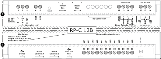
RP-C-12A, -12B, and -12C Models
Regulatory Compliance and Safety Information
Electrical equipment should be installed, operated, serviced, and maintained only by qualified personnel. No responsibility is assumed by Schneider Electric for any consequences arising out of the use of this material.
Carefully read these instructions and all information relevant for this product before trying to install it. See the list of technical literature.
The technical literature and declarations of conformity can be accessed on the Schneider Electric Exchange website, ecobuilding.schneider-electric.com. Contact your local Schneider Electric sales office for hard copy of documentation or for additional information.


 Danger


Part Numbers
|
Product |
Part number |
|
RP-C-12A-F-24V
|
SXWRCF12A10001
|
|
RP-C-12B-F-24V
|
SXWRCF12B10001
|
|
RP-C-12C-F-24V
|
SXWRCF12C10001
|
|
Optional covers
|
SXWRPCCOV10001
|
|
DIN-rail end clip, 25 pieces |
SXWDINEND10001 |
Specifications
| AC input | |
Nominal voltage
|
24 VAC

|
Power consumption
|
23 VA
|
| DC input | |
Nominal voltage
|
24 to 30 VDC

|
Power consumption
|
14 W
|
| Port types | |
USB device port
|
Mini-B
|
USB host port
|
Type-A, 5 VDC, 0.5 A
|
Ethernet port 1 and 2
|
10/100BASE-TX RJ45
|
Sensor bus
|
24 VDC, 2 W, RS-485 (RJ45)
|
Room bus
|
24 VDC, 3 W, RS-485 (RJ45)
|
| Wireless connectivity | |
Bluetooth
®
Low Energy (Bluetooth
®
5)
|
2.402 to 2.480 GHz, max. 10 dBm output power, 100 m (328 ft) line-of-sight range
|
Antenna
|
Integrated antenna
|
Approved external antenna (optional)
|
Manufacturer: Linx Technologies, Model: ANT-2.4-WRT-MON-SMA, Gain: 0.8 dBi, Type: Monopole, Impedance: 50 ohm, Connector: SMA
|
| Operation environment | |
Ambient temperature, operating
|
0 to 50 °C (32 to 122 °F) at normal operation
|
-40 to +60 °C (-40 to +140 °F) for rooftop applications, horizontal installation only
|
|
See section Installation Orientation Restrictions.
|
|
Humidity
|
Maximum 95 % RH non-condensing
|
| Mechanical | |
Ingress protection rating
|
IP 20
|
Plastic flame rating
|
UL94-5VB
|
| IP networking | |
IP address assignment methods
|
Static, DHCP, Auto-IP (address range 169.254.0.1 to 169.254.255.254, subnet mask 255.255.0.0)
|
| Regulatory compliance | |
EMC, safety, and environment
|
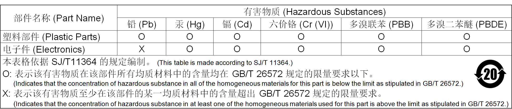
FCC (ID: DVE-RPC24), ISED (IC: 24775-RPC24), RCM, CE - RED 2014/53/EU, WEEE 2012/19/EU, RoHS 2011/65/EU and 2015/863/EU, China RoHS SJ/T 11364-2014, UL 916 Listed products for the United States and Canada (UL file E80146), UL 2043 (Approved for plenum installations)
|
| Ub – Universal I/O | |
Input rating
|
24 VDC
|
Voltage output rating
|
0 to 10 VDC
|
Channels
|
RP-C-12A: 8; -12B: 8; -12C: 4
|
| DO – Relay outputs | |
Relay contact rating
|
Pilot Duty (C300)
|
Min. current: 100 mA (5 VDC)
|
|
Resistive: 250 VAC
|
|
4 A (cos phi = 1)
|
|
Inductive: 250 VAC
|
|
4 A (cos phi = 0.4)
|
|
Channels
|
RP-C-12A: 0; -12B: 3; -12C: 3
|
| DO – High power relay outputs | |
Relay contact rating
|
Pilot Duty (B300)
|
Normally Open, resistive: 250 VAC
|
|
/ 24 VDC
|
|
Normally Closed, inductive: 250 VAC
|
|
/ 24 VDC
|
|
Channels
|
RP-C-12A: 0; -12B: 1; -12C: 1
|
| DO – Solid-state relay outputs | |
Output rating
|
30 VAC
|
Max. 4 A total load
|
|
Channels
|
RP-C-12A: 4; -12B: 0; -12C: 4
|
Addendum - California Proposition 65 Warning Statement for California Residents