Specifications
USB-485-INET Adapter

Introduction
The USB-485-INET adapter provides a communication gateway between an I/NET controller LAN and a SmartX AS-P server or an Automation Server. Using this gateway, you can discover I/NET devices directly within the EcoStruxure Building Operation software without the use of I/NET Seven host software. You can then add points from the I/NET devices to the projects you configure in the EcoStruxure Building Operation software.
Features
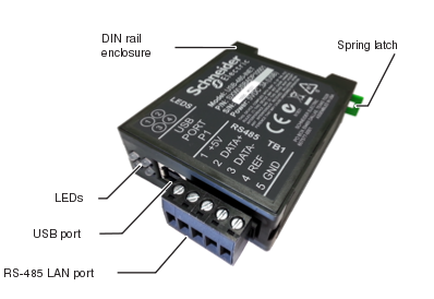
USB-485-INET provides the communication interface between the SmartX AS-P server's or Automation Server's USB port and the I/NET system RS-485 bus.

Install USB-485-INET on the DIN rail to the left side of the PS-24V power supply. The enclosure has a spring latch, which snaps onto the DIN rail and holds the adapter securely in place on the rail.
USB-485-INET communicates with and is powered by a SmartX AS-P server or an Automation Server through a USB type-B port. The adapter is delivered with a short custom length USB type-A to type-B cable. The cable length is 300 mm (12 inches), which matches the length needed to connect with a SmartX AS-P server or an Automation Server without excess cable to tuck away. The down angled type-B connector has a low profile to fit shallow depth enclosures. Use only the USB cable delivered with the adapter. Using a cable that exceeds the provided 300 mm (12 inches) length can cause communication interruptions or failures.
USB-485-INET uses a five-position plug-in terminal block TB1 for connection of the RS-485 I/NET controller LAN. The twisted pair cable from the RS-485 LAN is connected to the adapter using terminals 2 and 3 of terminal block TB1. The positive (+) wire of the pair connects to terminal 2 and the negative (-) wire connects to terminal 3. This polarity convention is recommended to accommodate standardized wiring connections between LAN nodes and support early model LAN repeaters.

USB-485-INET provides isolation between the RS-485 port and the electronics serving the internal processor and USB communication with the SmartX AS-P server or Automation Server. The adapter also provides suppression of transient currents and voltages for the pins of the RS-485 port and the USB port.
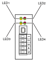
USB-485-INET has four bi-colored LEDs on the front of the adapter.

LED1 indicates errors detected on the RS-485 I/NET controller LAN. The LED flashes green when the adapter detects a CRC error in a reply from an I/NET controller. The LED flashes yellow when an I/NET controller fails to respond to the adapter.
LED2 indicates transmit (red) and receive (green) activity on the RS-485 LAN. When the adapter participates in the token passing traffic on the LAN, the LED continuously flashes red and green.
LED3 indicates poor data quality of the RS-485 LAN. The LED flashes yellow when the jitter (distortion) of the bit cell is greater than 24%. This does not mean that the LAN is necessarily experiencing errors or problems. It just means that the data quality is less than optimal and any errors detected on the LAN may be a by-product of the data quality. The quality issue is typically caused by excess cable length, high capacitance of the cable, exceeded node count, or faulty grounding of a node on the LAN. The green LED color is reserved for future use.
LED4 indicates the status of the USB connection. The LED flashes red when the adapter communicates with the SmartX AS-P server or Automation Server through the USB interface. The LED is green when the adapter is powered on, which indicates that the adapter successfully passed the power-on self-test and that the USB connection to the SmartX AS-P server or Automation Server is established.
The terminal block receptacle TB2 and the BSL (Bootstrap Loader) push button S1 are located on the top of the adapter. The receptacle is intended for special diagnostic purposes not pertaining to this application. The BSL push button provides a means to load new firmware into the adapter from a PC connected to the USB port.
Specifications
| Electrical | |
DC input current consumption
|
Maximum 0.3 A
|
Typical 0.1 A
|
|
DC input supply voltage
|
5 VDC (USB)
|
| Environment | |
Ambient temperature, operating
|
0 to 50 °C (32 to 122 °F)
|
Ambient temperature, storage
|
-20 to +70 °C (-4 to +158 °F)
|
Maximum humidity
|
95 % RH non-condensing
|
| Material | |
Plastic rating
|
UL94-V0
|
Enclosure
|
Polyamide 66 (PA66)
|
Enclosure rating
|
IP 20
|
| Mechanical | |
Dimensions
|
22.5 W x 60 H x 75 D mm (0.9 W x 2.4 H x 3.0 D in.)
|

|
|
Weight
|
53.9 g (1.9 oz.)
|
| Agency compliances | |
Emission
|
RCM; FCC Part 15, Sub-part B, Class B
|
Product
|
EN 61326-1
|
| Communications | |
USB port
|
USB 2.0, type-B connector
|
RS-485 LAN port
|
Isolated interface
|
Failsafe transceiver (does not require LAN bias)
|
|
¼ unit load maximum
|
|
Fault-protected transceiver
|
|
Supports high common-mode voltage (20 V)
|
|
RS-485 LAN data
|
19,200 or 9600 bit/s
|
SDLC NRZI format
|
|
Token passing bus
|
|
Up to 64 LAN nodes
|
|
RS-485 LAN bias
a
|
+5 V and REF
|
| a) For future applications (not required for I/NET controller LAN) | |
| Part numbers | |
USB-485-INET adapter
|
SXWUSBADP10001
|
 Updating the USB-485-INET Adapter Firmware