-
Content
arrow2_down -
Basic Functionality
-
Alarms
-
Trends
-
Schedules
-
Graphics
-
Dashboards
-
Reports
-
Registration
-
User Management
-
License Management
-
Localization
-
Zoning
-
Semantic
-
Sustainability
-
Engineering
-
Administration
-
Custom Types
-
Import/Export
-
Programming
- Communication Configuration
-
Security
-
Hardware
- SpaceLogic Sensor Interfaces
-
Upgrade
- Transition
-
Smoke Control
-
WebStation
-
WorkStation
-
Registration Portal
- Touch Screens
-
Engage
-
Enterprise Central
-
Enterprise Server
- Automation Servers
-
License Server
- Administrator Tools
- BACnet/IP Devices
- RP Controller Expansion Modules
-
Wireless Adapter - Advanced
-
SpaceLogic Sensors
- Power Supply
- Central IO Modules
-
Builder View
-
Graphics Editor
-
Script Editor
-
Builder for Function Block
-
Function Block Editor
-
Project Configuration Tool
-
Virtual Project Servers
- Mobile Apps
-
Support Tools
-
TAC Vista Conversion Tool
-
Continuum Conversion Tool
-
WebReports
-
WebHelp
- WebHelp Overview
- Safety Information
Functionality
Products

How to
Wiring the Screw Terminals on an RS-485 Power Adapter for Connection to an RS-485 Bus
You wire the screw terminals on an RS-485 Power Adapter to connect a BACnet/IP controller (RP or MP controller) to an RS-485 bus. Always use the recommended wires.
The RS-485 Power Adapter can be used to convert a BACnet/IP controller (RP or MP controller) RS-485 interface from RJ45 port to screw terminals, which is required to be able to connect the controller to an RS-485 based network such as a Modbus RTU network. The types of RS-485-based networks supported differ between the different RP and MP controller models.
Through the RS-485 Power Adapter, 24 VDC can also be distributed from the BACnet/IP controller RS-485 interface to a device on the RS-485 bus.
| Notice |
|---|
|
EQUIPMENT DAMAGE OR LOSS OF COMMUNICATION Do not use the adapter to connect an MP or RP controller to a BACnet MS/TP (RS-485) bus for communication with an automation server. Failure to follow these instructions can result in equipment damage or loss of communication. |
You should not use the RS-485 Power Adapter to connect an MP or RP controller to a BACnet MS/TP (RS-485) network, even if there is nothing preventing you from physically connecting the adapter to such a network, as it can cause ground loops and poses a risk of miswiring of 24 VDC and bias terminals.
Examples
This section gives two examples of how the adapter can be used to convert an RP controller RS-485 interface:
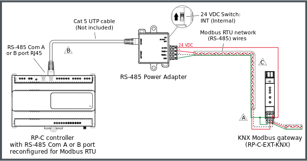
Example with an RP-C controller and a KNX Modbus gateway
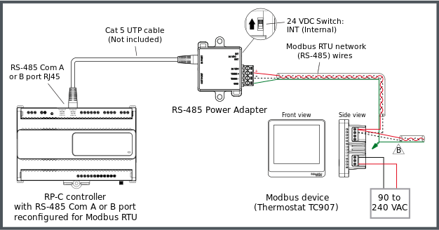
Example with an RP-C controller and a standard Modbus device
The RP controller Modbus network supports up to 10 connected Modbus devices with the following restrictions:
Maximum of one KNX Modbus gateway (RP-C-EXT-KNX)
Maximum of 250 Modbus registers per network
The following figure shows an example of how an RS-485 Power Adapter is connected to one of the RS-485 Com ports (RJ45) of an RP-C controller via a Cat 5 (or higher) UTP cable and how the Modbus RTU network twisted pair wires from the adapter are connected to the screw terminals of a KNX Modbus gateway (RP-C-EXT-KNX), which is powered by the controller via the adapter. Additional Modbus devices may be daisy-chained from the KNX Modbus gateway.
The twisted pair cable used for TX/RX+ and TX/RX- data wires extends in one direction from the adapter to each device in a daisy chain bus configuration without cable stubs.
For more information, see KNX Modbus Gateway Screw Terminals and Connector .


The following figure shows an example of how the Modbus RTU network twisted pair wires from the adapter are connected to the screw terminals of a standard Modbus device, which is powered by a separate power supply. In this example, the Modbus device is a thermostat from the SpaceLogic Thermostat TC907 Series. Additional Modbus devices may be daisy-chained from the thermostat.
The twisted pair cable used for TX/RX+ and TX/RX- data wires extends in one direction from the adapter to each device in a daisy chain bus configuration without cable stubs.


Connection of RJ45 Port to BACnet/IP Controller RS-485 Com Port
A separate connection cable is required to connect the RJ45 port on the RS-485 Power Adapter to the RS-485 Com port (RJ45) on the BACnet/IP controller (RP or MP controller). The cable is not included and needs to be purchased separately.
Use a Cat 5 (or higher) unshielded, straight-through wired cable with eight conductors (four twisted pairs) and RJ45 connectors. Use a cable with the wire size (cross-sectional area) 22 to 26 AWG (0.34 to 0.14 mm²), and a rating that meets the requirements of the target environment. For example, when devices are installed in a space that handles conditioned air or return air, the cables typically need to be plenum-rated.
| Notice |
|---|
|
LOSS OF COMMUNICATION Use a Cat 5 or higher unshielded twisted pair cable with eight conductors (four twisted pairs), a cross-sectional area of 22 to 26 AWG (0.34 to 0.14 mm 2 ), and a rating that meets the requirements of the target environment. Failure to follow these instructions can result in loss of communication. |
| Notice |
|---|
|
LOSS OF COMMUNICATION Ensure that the total length of the RS-485 bus, from the controller to the end of the bus, does not exceed the following limit:
Failure to follow these instructions can result in loss of communication. |
For more information, see Connecting an RS-485 Power Adapter to Convert a BACnet/IP Controller RS-485 Interface .
For more information, see Communication Port Wiring .
For more information, see RJ45 Pinout for the RS-485 Ports of the RP-C Controller .
For more information, see RJ45 Pinout for the RS-485 Port(s) of the RP-V Controllers .
For more information, see RJ45 Pinout for the RS-485 Port of the MP-V Controller .
Wiring of Screw Terminals for Connection to RS-485 Bus
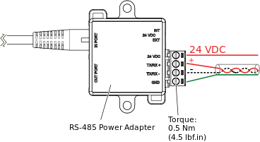
The four screw terminals are wired and connected to an RS-485 bus as described in the following table.
Recommended screw tightening torque: 0.5 Nm (4.5 lbf.in)
Table: Screw Terminals, RS-485 Power Adapter, Connection to RS-485 Bus
|
Terminal |
Usage |
|
Terminal |
Usage |
|
24 VDC |
Connected only when a device on the RS-485 bus requires 24 VDC power supply from the RP or MP controller. For example, the KNX Modbus gateway (RP-C-EXT-KNX) can be powered by an RP controller. Not connected in all other cases.
|
|
TX/RX+ |
Data line (+) for connection to the TX/RX+ signal in the RS-485 twisted pair connecting all devices on the RS-485 bus. |
|
TX/RX– |
Data line (–) for connection to the TX/RX– signal in the RS-485 twisted pair connecting all devices on the RS-485 bus. |
|
GND |
Ground terminal for connection to the signal ground and power ground of the controller. |
For more information, see Wiring the Screw Terminals on an RS-485 Power Adapter for Connection to an RS-485 Bus .
For more information, see RS-485 Communications .
| Notice |
|---|
|
EQUIPMENT DAMAGE OR LOSS OF COMMUNICATION Do not use the adapter to connect an MP or RP controller to a BACnet MS/TP (RS-485) bus for communication with an automation server. Failure to follow these instructions can result in equipment damage or loss of communication. |
| Notice |
|---|
|
LOSS OF COMMUNICATION Ensure that the total length of the RS-485 bus, from the controller to the end of the bus, does not exceed the following limit:
Failure to follow these instructions can result in loss of communication. |
Loosen the screw of the terminal.
Strip approximately 7 mm (0.3 inch) of the insulation from the end of each wire.
Insert the end of the wire fully into its intended terminal. Ensure that no bare wire strands extend from the terminal.
Tighten the screw using a small flat-blade screwdriver. Ensure that the screw is fully tightened. Use the following recommended screw tightening torque: 0.5 Nm (4.5 lbf.in).
Repeat steps 1 to 4 until all screw terminals on the adapter are correctly wired. For more information, see RS-485 Power Adapter Ports, Terminals, and Switch .
Follow the recommendations and guidelines for the RS-485 interface configuration in regard to biasing, termination, cable selection, cable length, and cable routing. For more information, see RS-485 Communications .
Note:Wire the 24 VDC terminal on the adapter only when a device on the RS-485 bus requires 24 VDC power supply from the RP or MP controller.
action_zoom_plus_stroke 
Ensure that the total length of the RS-485 bus, from the RP or MP controller to the RS-485 device at the end of the bus, does not exceed the following limit:
Modbus: 72 m (236 ft)
Use appropriate cable strain relief methods, to help prevent any load applied to the cable from being transferred to conductor terminations.
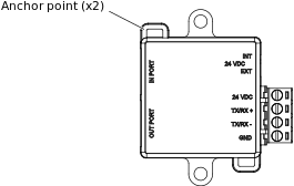
You can use the anchor points on the adapter enclosure and cable ties to fasten and fix the cables.
action_zoom_plus_stroke 
See Also
 Convert a BACnet/IP Controller RS-485 Interface
 Connecting an RS-485 Power Adapter to Convert a BACnet/IP Controller RS-485 Interface
 Installing an RS-485 Power Adapter
 Wiring
 RS-485 Communications