
How to
Wiring a Terminal Base
You can wire a terminal base prior to installing an electronics module.
The Building Operation devices are designed mainly for installing on DIN rails in a cabinet. Consider a simple example:
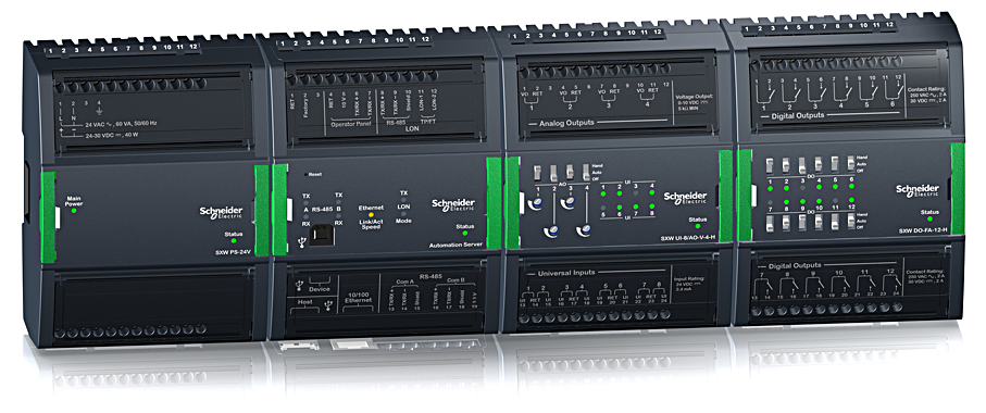
Each Building Operation device consists of two parts:
Terminal base
Electronics module
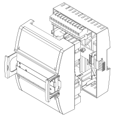
The terminal base is normally fixed to a DIN rail. The electronics module is easily plugged in to the terminal base and firmly locked by pushing the convenient handles in place.
There is a great advantage in having a separate terminal base; the terminal base can be installed and wired long before the electronics module with the application program and data is supplied.
Replacing an electronics module is done in seconds since no terminal wiring is affected.
However, different electronics modules may require different types of terminal bases. It is vital to put the electronics module in the correct type of terminal base; failure to do so may lead to malfunctioning devices and/or exposure to dangerous voltage.
An overview of the electronic modules and their corresponding terminal base is listed in a table.
DIN Rail Installation
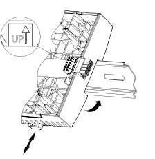
The hardware devices are installed on the same DIN rail, with the power supply to the far left.
The devices to the right of the power supply get their power through a terminal base (the back plane) in each device, which automatically connects when the device (rather, the terminal base) is installed close to the previous device.
To ensure that the correct electronics module is used with the correct terminal base, you must always check that the warning label shows which device is to be connected. Write the intended module type, if it is not already printed, on the label.
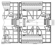
 Warning
When several DIN rails are needed, an S-cable is used to connect the devices of two succeeding rails.
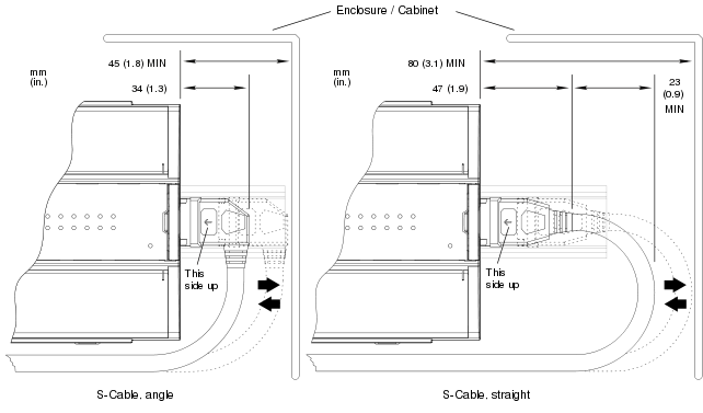
Installation Sequence
Devices should be installed in the following order:
The first device (position 1 on the I/O bus) must always be a power supply.
The Automation Server (only one) must always occupy position 2.
I/O modules must be installed after (‘to the right of’) the server (position 3-32).
Additional power supplies can be added when needed. They provide power to succeeding devices in the sequence.
The rules can also be summarized in an illustration:
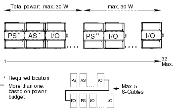
Each device automatically gets an address, from 1 to 32, corresponding to its physical position (slot) and start with 1 in the upper leftmost position.
In some cases, it may be necessary to prevent the modules from sliding sideways on the DIN rail. If required, fix an end clamp for DIN 35 tightly against the rightmost device on the rail. The sliding locks are available in batches of 25.
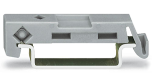
The end clamp is easily removed if you bend the snap lock open with a screwdriver.
 Danger
 Notice
Wiring can also be carried out after a module has been installed in its terminal base.
To access the terminal block screws, remove the electronics module or open the clear plastic label carrier.
action_zoom_plus_stroke Loosen the screws of the terminal block.
Strip approximately 7 mm (0.3 inch) of the insulation from the end of each wire.
Insert the stripped end of each wire fully into its intended terminal. Ensure that no bare wire strands extend from the terminal.
Tigthen the screws using a small flat-blade screwdriver. Ensure that the screws are fully tightened. Use the following recommended screw tightening torque: 0.56 Nm (5 lbf.in).
Close the top clear plastic label carrier or refit the electronics module.
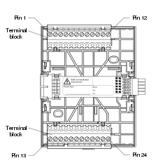
 DIN Installation
Wiring
 Printing a Wiring List for the I/O Bus