Concepto
External Device Connections
There are many different kinds of external devices from different vendors that can be connected to an EcoStruxure BMS.
It is important to know how different external devices cooperate with the devices in the EcoStruxure BMS, so we present some different principles for those external devices here. As a rule of thumb, try to avoid direct connections between RET and G0 external to the control panel. As discussed below, if a signal ground rail (SGR) is used, one RET pin on each I/O module and SmartX IP Controller device should be wired to the SGR in the control panel using 1.3 mm² (16 AWG) or larger wire. For SmartX AS-B servers, the RET terminals 4 and/or 5 can be used for connection of the SGR. For good performance, use as short and large wires as possible.
Thermistors
Thermistors are connected directly between a universal input terminal and the corresponding RET terminal.

Contacts
Digital inputs are controlled by contact closings to RET. The digital inputs are normally quite immune to disturbance signals, so they can also detect contact closings directly to the signal ground rail or G0. Even though RET is connected to the signal ground rail, there might be a small voltage difference that could impact results on analog inputs. Such small voltage differences are not enough to impact digital inputs though.

Actuators
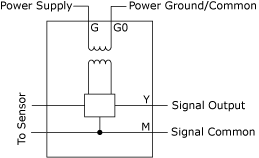
Actuators are divided into two types: isolated and non-isolated control voltage actuators. The non-isolated actuators are more commonly used. The two actuator types work mostly in the same way, but the non-isolated actuators have the signal ground M internally connected to power ground G0. In some cases, they have only three terminals with one common terminal for M and G0.


Non-isolated actuators can be more sensitive to different kinds of disturbances, and it is sometimes easier to design a more stable system using isolated actuators. When the system uses a non-isolated actuator, care must be taken in properly wiring the neutral wire back to the supply neutral for each actuator rather than daisy chaining to help prevent large voltage drops that can affect input signal accuracy.
Some actuator control signal inputs may be designed with a high impedance differential input which helps prevent AC/DC supply currents from being shared in the signal return path. Such actuators are as good as isolated actuators with respect to disturbances and ground currents, so they can be connected as isolated actuators.
The disturbance can be of two kinds: AC disturbance causing the actuator to move quickly back and forth, and DC disturbance causing an offset. Both AC and DC issues occur as a result of currents in the connection from M to RET.
The DC issue is a less severe problem because a DC error can be compensated by the control loop as long as the error is quite small. If the DC error is big, the actuator may not be able to turn off or on completely. Normally the actuator starts to open when the control voltage is a few hundred millivolts, so a DC offset of 100 mV is probably not an issue.
The AC issue can be a more severe problem. If an AC disturbance is added to the control signal, the actuator starts to travel back and forth and its dependability may be affected.
If it is unknown whether an actuator is isolated or non-isolated, it should be treated as non-isolated.
For non-isolated actuators, difficult problems with disturbances can sometimes be solved by introducing a separate isolated transformer for the actuator. In this way, you can obtain an isolated system with a non-isolated actuator.

Transmitters
Transmitters are used to convert signals from sensors that cannot be connected directly to an I/O module, SmartX AS-B server, or SmartX IP Controller device. Transmitters are divided into two types: isolated and non-isolated transmitters.


When the system uses a non-isolated transmitter, AC and DC bias issues may occur.
The DC error from a voltage transmitter can never be compensated for by a feedback loop. So, a DC current in the M conductor causes a DC error in the reading value if the current and the resistance are large enough to cause a non-negligible voltage drop, thus creating an error. An AC voltage drop caused by an AC current in the conductor between M and RET results in unstable measurements.
Selecting isolated transmitters solves the AC and DC bias issues, but the issues can also be limited by good system design. Para obtener más información, consulte Grounding and Power .
In isolated transmitters, the sensors are normally not isolated from the M conductor, they are only isolated from the power supply of the transmitter. This is not an issue, because the sensors are not connected to anything but the transmitters.
Transmitters may have differential outputs. Transmitters with differential outputs can be connected as isolated external devices.
If it is unknown whether a transmitter is isolated or non-isolated, it should be treated as a non-isolated transmitter.
The use of current (4-20 mA) transmitters (instead of voltage output) avoids error from DC voltage drop in the common M to RET return wiring and assists in reducing signal reading instability from AC current in the return path.
For non-isolated transmitters, difficult problems with disturbances can sometimes be solved by introducing a separate isolated transformer for the transmitter. In this way, you can obtain an isolated system with a non-isolated transmitter.

Loads Such as Relays
Relay outputs are isolated from the signal ground. Therefore, no special care must be taken with respect to grounding in this case.
 Hardware Overview
 I/O Modules
 SmartX AS-B Servers
 MP-Cs
MP-Cs
 MP-Vs
MP-Vs
 IP-IO Modules
 RP-Cs
RP-Cs
 Wiring
 I/O Wiring
 Grounding and Power