Concept
MNB Configuration 1: Dual End-point Bias (MNB Source)
Dual end-point bias applies a separate 5 V DC supply at each end of the network to generate the RS-485 bias. Instead of a single pair of 510 ohm resistors, the dual end scheme uses a pair of 1000 ohm resistors at each end. The dual end-point is the best technique for avoiding the drop in the bias voltage over extended cable lengths as you move away from the bias connection location. By applying the bias at the same location as the termination, the arrangement maintains an equal bias across the complete length of the cable. This technique avoids the positional sensitivity of Configuration 3 in locating the middle point of the network and provides a superior bias reliability. Pour plus d'informations, voir MNB Configuration 3: Mid-point Bias . This Configuration 1 differs from Configuration 2 only in the use of MNB-300 or MNB-1000 devices to provide the bias supply source. Pour plus d'informations, voir MNB Configuration 2: Dual End-point Bias (External Supply Source) .
Configuration 1 can be used when you have the following arrangement of bias supply sources:
MNB-300 or MNB-1000 device at the far end of the bus
AS-P server or AS-B server at the head end of the bus
The bias supply sources must be located at the two ends of the MS/TP network bus or within 60 m (200 ft) of the end of the cable. If an MNB-300 or MNB-1000 device is used for bias and the device is not positioned at the actual end of the bus, the EOL termination jumper selection must not be used on the MNB device. Only the biasing pin header/connector position will be used, and the EOL 120 ohm termination resistor must be attached across the + and – bus pair on the device positioned at the actual end of the cable.
The recommended power supplies to use with the automation server are discussed separately. Pour plus d'informations, voir Power Supply Selection for MNB Configuration 1, 2 and 3 .
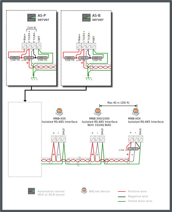
Connect a 1000 ohm bias resistor from the TX/RX+ terminal (see the figure below) to the Bias+ terminal on the AS-P server or AS-B server. Connect another 1000 ohm bias resistor from the TX/RX- terminal to the RET terminal on the AS-P server or AS-B server.
Connect a 120 ohm termination resistor across the + and - data lines at the head end of the bus (typically at the automation server). Connect another 120 ohm termination resistor across the + and - data lines on the last node at the far end of the bus.
Connect the shield drain wire to earth ground terminal rail in the panel with the automation server. This is the only ground connection of the shield for the complete cable segment. Connect the RET terminal on the automation server to the ground rail in the control panel using a 12 AWG (3.31 mm²) to 18 AWG (0.82 mm²) wire. The shield drain wires from the cable segments are connected to the RS-485 SHLD terminal at each MNB BACnet device.
Use only the terminal block designated for MS/TP communications for Shield connection.
The example diagram below shows the alternate RS-485 terminal block connections for the different automation server models.
The example diagram below shows the RS-485 Com B connections on the AS-P and AS-B servers. The guidelines are the same for Com A.

As an alternative to using the AS-P server or AS-B server Bias+ terminal to provide the head-end bias (as shown in the figure above), the network bias can be provided from an MNB-300 or MNB-1000 device located within 60 m (200 ft) of the network head end.
If an MNB-300 or MNB-1000 device is positioned at the end of the bus, the termination option jumper on the device may be enabled, instead of attaching a 120 ohm resistor on the terminal block. This also applies to the head end of the bus if a MNB-300 or MNB-1000 device is positioned there instead of a typical automation server.
The recommended maximum cable length is 1200 m (4000 ft), if using a 24 AWG (0.20 mm²) or larger cable.
The preferred location for the bias is at the two extreme ends of the network cable, but the bias voltage remains effective if applied within 60 m (200 ft) from the end. This configuration supports the preferred termination resistor values of 120 ohm with one positioned at each end of the cable. The unit load imposed by the dual end-point bias is 23.5UL (12,000 / 510).
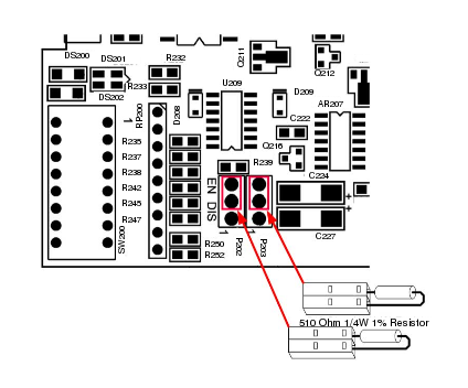
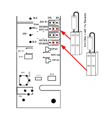
The MNB-300 or MNB-1000 devices being used to provide the network bias must be configured with plug-on 510 ohm resistors instead of the typical plug-on shorting connector. The plug-on resistors are available in packages of 50 with a part number of MNB-BIAS510-50. Two of the plug-on resistors are attached to each of the MNB devices. This arrangement creates a 1020 ohm bias from the network end.
On the MNB-300 device, remove any existing plug-on shunt connectors from pin header positions P202 and P203. Press a plug-on 510 ohm resistor onto the EN (enable) position of pin headers P202 and P203. This is the top two pins on those two headers as seen in the following diagram.

On the MNB-1000 device, remove any existing plug-on shunt connectors from pin header positions P102 and P105. Press a plug-on 510 ohm resistor onto the EN (enable) position of pin headers P102 and P105. This is the right-hand two pins on those two headers as seen in the following diagram.

 MNB BACnet Devices
 MNB Configurations
 MNB Configuration 2: Dual End-point Bias (External Supply Source)
 MNB Configuration 3: Mid-point Bias