Concepto
MNB Configuration 2: Dual End-point Bias (External Supply Source)
When MNB-300 or MNB-1000 devices are not available within 60 m (200 ft) of the end of the cable, the dual end-point bias configuration can still be deployed as seen here in Configuration 2 using a separate 5 V DC supply at each end of the network to generate the RS-485 bias. The same as Configuration 1, this arrangement provides the best performance on systems where bias is needed. Para obtener más información, consulte MNB Configuration 1: Dual End-point Bias (MNB Source) . The dual end-point avoids the drop in the bias voltage seen with the single end-point bias arrangements. By applying the bias at the same location as the termination, the arrangement maintains an equal bias across the complete length of the cable. This technique does not encounter the positional sensitivity of Configuration 3 in locating the middle point of the network. Para obtener más información, consulte MNB Configuration 3: Mid-point Bias .
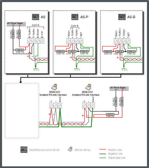
When using AS-P or AS-B, and the server is positioned at the head end of the network, you can use the 5 V available on the Bias+ terminal to provide the head-end bias. You use an external 5 V DC power supply to provide the bias at the far end of the network. When using Automation Server, you use external 5 V DC power supplies at both ends of the network to provide the network bias. The recommended power supplies are discussed separately. Para obtener más información, consulte Power Supply Selection for MNB Configuration 1, 2 and 3 .
Connect a 1000 ohm bias resistor from the TX/RX+ terminal (see the figure below) to the 5 V bias supply (connect the resistor to the Bias+ terminal on AS-P or AS-B, or to the positive terminal on the external 5 V DC power supply). Connect another 1000 ohm bias resistor from the TX/RX- terminal to the 5 V bias supply (connect the resistor to the RET terminal on AS-P or AS-B, or to the negative terminal on the external 5 V DC power supply). Connect an external 5 V DC power supply to the MS/TP bus pair through two 1000 ohm bias resistors at the far end of the cable.
Connect a 120 ohm termination resistor across the + and - data lines at the head end of the bus (typically at the SmartStruxure server device). Connect another 120 ohm termination resistor across the + and - data lines on the last node at the far end of the bus.
Connect the shield drain wire to earth ground terminal rail in the control panel with the SmartStruxure server device. This is the only ground connection of the shield for the complete cable segment. Connect the RET/Shield terminal on the SmartStruxure server device to the ground rail in the panel using a 12 AWG (3.31 mm²) to 18 AWG (0.82 mm²) wire. The shield drain wire from the cable segments are connected to the RS-485 SHLD terminal at each MNB BACnet device.
Use only the terminal block designated for MS/TP communications for Shield connection.
The example diagram below shows the alternate RS-485 terminal block connections for the different SmartStruxure server device models.
The example diagram below shows the RS-485 Com B connections on Automation Server and AS-P. The guidelines are the same for Com A.

If an MNB-300 or MNB-1000 device is positioned at the end of the bus, the termination option jumper on the device may be enabled, instead of attaching a 120 ohm resistor on the terminal block. This also applies to the head end of the bus if a MNB-300 or MNB-1000 device is positioned there instead of a typical SmartStruxure server device.
The recommended maximum cable length is 1200 m (4000 ft), if using a 24 AWG (0.20 mm²) or larger cable.
The recommended location for the separate supply bias is at the two extreme ends of the network cable, but the bias voltage remains effective with a 60 m (200 ft) tolerance on the cable length from the end. This configuration supports the preferred termination resistor values of 120 ohm with one positioned at each end of the cable. The unit load imposed by the dual end-point bias is slightly higher with 24UL (12,000 / (1,000 / 2) = 24) instead of 23.5UL (12,000 / 510).
 MNB BACnet Devices
 MNB Configurations
 Power Supply Selection for MNB Configuration 1, 2 and 3
 MNB Configuration 1: Dual End-point Bias (MNB Source)
 MNB Configuration 3: Mid-point Bias