Concepto
MNB Configuration 3: Mid-point Bias
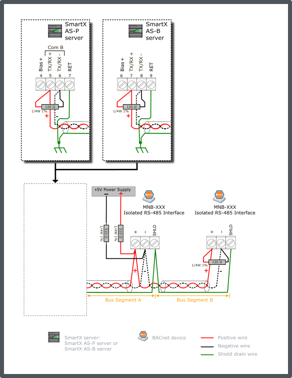
Mid-point bias refers to the technique of using a separate 5 V DC power supply and locating it at the middle of the total network cable length. This technique takes advantage of the maximum DC differential resistance at the center to maximize the bias voltage applied through the typical pair of 510 ohm resistors from the 5 V bias supply. The higher bias voltage level now applied in the center can extend up to 600 m (2000 ft) in both directions from the center using 24 AWG (0.20 mm²) size cable (or larger).
Position an external 5 V DC power supply at the middle of the total MS/TP network length. Connect the supply to the MS/TP bus pair through two 510 ohm resistors. The recommended power supplies are discussed separately. Para obtener más información, consulte Power Supply Selection for MNB Configuration 1, 2 and 3 .
Connect a 120 ohm termination resistor across the + and - data lines at the head end of the bus (typically at the SmartX server). Connect another 120 ohm termination resistor across the + and - data lines on the last node at the far end of the bus.
Connect the shield drain wire to earth ground terminal rail in the control panel with the SmartX server. This is the only ground connection of the shield for the complete cable segment. Connect the RET terminal on the SmartX server to the ground rail in the panel using a 12 AWG (3.31 mm²) to 18 AWG (0.82 mm²) wire. The shield drain wires from the cable segments are connected to the RS-485 SHLD terminal at each MNB BACnet device.
Use only the terminal block designated for MS/TP communications for Shield connections.
The example diagram below shows the alternate RS-485 terminal block connections for the different SmartX server models.
The example diagram below shows the RS-485 Com B connections on the SmartX AS-P and AS-B servers. The guidelines are the same for Com A.

As alternatives to using an external 5 V DC power supply to provide the mid-point bias (as shown in the figure above), the following two bias supply options can be used:
If a bias-capable MNB-300 or MNB-1000 device is positioned at the middle point in the network, the MNB device's bias option can be used to provide the mid-point bias.
If a SmartX AS-P server or SmartX AS-B server is positioned at the middle point in the network, the server's 5 V bias supply output can be used to provide the mid-point bias. The server is configured as in Configuration 2, except the cable extends in both directions away from the server with equal lengths. ( Para obtener más información, consulte MNB Configuration 2: Dual End-point Bias (External Supply Source) .)
If an MNB-300 or MNB-1000 device is positioned at the end of the bus, the termination option jumper on the device may be enabled, instead of attaching a 120 ohm resistor on the terminal block. This also applies to the head end of the bus if a MNB-300 or MNB-1000 device is positioned there instead of a typical SmartX server.
If an MNB-300 or MNB-1000 is used to provide the single point bias, the standard plug-on shunt connectors are used to achieve the bias. The plug-on resistor (MNB-BIAS510-50) is only used in Configuration 1.
The recommended maximum cable length is 1200 m (4000 ft), if using a 24 AWG (0.20 mm²) or larger cable.
The mid-point location selected for the bias should be within ±60 m (±200 ft) of true middle of the cable length. In other words, the mid-point bias divides the network bus in two segments (named A and B in the above figure), which should be approximately equal. The remote end bias voltage will drop significantly as the bias location moves away from network center.
This configuration supports the preferred End Of Line (EOL) termination resistance value of 120 ohm. The 120 ohm termination resistors must be positioned on the two ends of the network. The unit load imposed by the mid-point bias is the same as for Configuration 1, 2, 4 and 5, and the discussion on node count calculation is the same. Para obtener más información, consulte MNB Configurations .
Configurations 1 or 2 are preferred over Configuration 3 due to the need for Configuration 3 to maintain a length balance on either side of the bias location. Later network revisions can easily disrupt the bias performance by either adding or reducing cable length on either side of the bias location (without performing the same change on the other side). This presents a counter-intuitive result from later work on the system. A person would typically think that no harm could be encountered by reducing the length of a network. In most cases, the system will probably continue to operate, but the noise margin will have been reduced by less than specified bias now presented to a collection of devices. Such scenarios offer a tendency to go unnoticed and show up later as communications anomalies possibly thought to be related to later actions that should not have such impact, but are sufficient to compromise a situation that now is forgotten.
Para obtener más información, consulte MNB Configuration 1: Dual End-point Bias (MNB Source) .
Para obtener más información, consulte MNB Configuration 2: Dual End-point Bias (External Supply Source) .
 MNB BACnet Devices
 MNB Configurations
 Power Supply Selection for MNB Configuration 1, 2 and 3
 MNB Configuration 1: Dual End-point Bias (MNB Source)
 MNB Configuration 2: Dual End-point Bias (External Supply Source)
 MNB Configuration 4: Single End-point Bias (SmartX Server Provided Source)