Concetto
Unit Load Definition, Maximum Network Load and Affects of Excess Unit Load (Viconics VT/VZ7xxx Devices)
According to the TIA-485A standard, a single unit load is equivalent to a 12 kohm impedance attached to the + and – data lines (connected to ground or supply). A 1/8UL transceiver would have an impedance of 96 kohm. The TIA-485A defined total network load limit of 32UL is based on a common mode load resistance of 375 ohm connecting both the + and – data lines to ground (or CMV source). The standard requires the RS-485 drivers be capable of driving a network load of 32UL along with a Common-Mode Voltage (CMV) difference of -7 V to +12 V and produce a guaranteed minimum of 1.5 V transmit signal level. Such a full UL load with severe CMV conditions exhausts the maximum drive current of 60 mA provided by all standard RS-485 drivers. The specified minimum of 375 ohm resistance for the common mode load is the resulting resistance seen when 32 transceivers with 12 kohm input impedance are placed in parallel (12,000 / 375 = 32).
The TIA-485A standard does not accommodate any special allowance or exclusion for the addition of bias resistors. If you add load to the data lines (for whatever purpose), it is part of the common mode load and must be considered in the calculation of unit load on the network. In the same manner that 375 ohm equals 32UL, 510 ohm resistance equals 23.5UL.
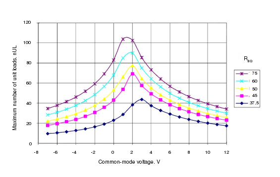
The accumulation of RS-485 node counts in excess of the standard defined limit of 32UL does not alone create a violation prompting immediate inoperability. The primary performance parameter affected by network load is the ability of the RS-485 transmitter to output the minimum specified signal level of 1.5 V. Reduction in output signal level starts with the addition of the first load connected and reduces further as additional load is added. The 32UL boundary is simply the standardized guaranteed specification limit where the manufacturers guarantee the signal level will not have reduced below 1.5 V. As mentioned above, the 1.5 V signal output is guaranteed not only with a 32UL load, but also with an elevated common mode voltage (CMV of -7 V to +12 V). As the network exceeds the 32UL limit, the tolerance for this CMV will decay. The following graph from the TIA-TSB-89-A standards document shows the expected reduction in CMV as a function of unit load on the bus.

The REQ legend in the figure above refers to the resulting parallel load resistance of two termination resistors. The common 120 ohm termination produces 60 ohm and is shown by the REQ=60 cyan colored line. The cyan line indicates a standard UL load limit of 32 with a CMV between -7 V and +12 V. Extra current is required from the transmitter to overcome the common mode voltage seen through the common mode load impedance (unit load). As node count elevates, the tolerance for CMV pulls in as seen in the graph.
For example, if we accumulate the unit load from a collection of 63 RS-485 controller nodes each presenting a 0.62UL load, then we would have a device load of 39.06UL. When we add that to the 24UL of the 510 ohm bias network with the SmartStruxure server device, we now have a total network load of 63.06UL. In a configuration with 63 VT7000 devices we would have a load almost twice (197%) the standard recommended load limit of 32UL. From the figure above you can see that the specified minimum -7 V CMV will be expected to reduce to 0 V and the normal +12 V CMV support will reduce to about +3.5 V. All CMV reserve drive capacity has been completely exhausted. When operating in a situation where CMV is avoided, the reduction in transceiver CMV performance can be better tolerated. An isolated RS-485 bus configuration (such as with the VT7xxx sensors) allows the nodes to be insulated from local ground voltage differences which are a main source of sustained CMV on the bus. The isolated bus allows each of the transmitters to move up/down to the idle voltage of the bus.
 RS-485 Communications
 Viconics VT/VZ/SE 7xxx Series Devices