Концепт
General Viconics VT/VZ7xxx Device Properties
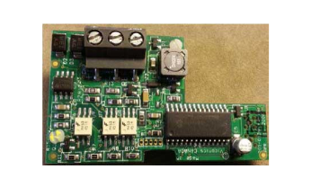
The RS-485 transceiver encountered on the Viconics MS/TP adapters reviewed was the STM ST485C. This transceiver alone has a RS-485 unit load rating of 0.5. With consideration only for the transceiver unit load, the 0.5 unit load rating would indicate up to 64 units transceivers could be attached to a single RS-485 network wire segment. This is the unit load and node limit described in Viconics' documents. The network adapter includes an on-board weak bias resistor of 100 kohm on the A+ and B- bus signals. This added 100 kohm resistance presents an additional unit load of 0.12UL making each of the controllers have an aggregate unit load of 0.62. This is the value that should be used in totaling the network load.

The transceiver used on the network adapter does not include an integrated failsafe receiver function. This means network biasing resistors are required on the RS-485 bus to insure the idle state of the bus is kept at a minimum of +200 mV (plus a noise buffer such as 25 to 50 mV). The recommended configuration of bias resistors are not discussed in Viconics' documents with the exception of a single line entry in the table referenced as Summary of Specifications for a Viconics' EIA-485 Network.
|
Parameter |
Details |
|
Network Bias Resistors |
510 ohm per wire (maximum of two sets per segment) |
A 510 ohm pull-up resistor on the RS-485 A+ line and a 510 ohm pull-down resistor on the B- line is consistent with the typical recommendations when strong biasing is required. A strong (low resistance) bias is required due to the recommendation for bus termination resistors. The Viconics specification summary mentions a maximum of two sets per segment. The connection of two instances of 510 ohm is not recommended, due to loading issues. The single 510 ohm bias has significant negative affect with 24UL unit load consumption. Two sets would consume 150% of standard unit load capacity without adding the first controller. Dual end biasing with a higher resistance is a recommended. Более подробную информацию см. VT/VZ7xxx Configuration 2: Dual End-point Bias (External Supply Source) .
The RS-485 circuitry on the network adapter is found to provide an isolated interface. The DC common used by the RS-485 transceiver is isolated from the local ground potential. This isolated DC common created by the isolated DC power supply on the adapter is presented on the terminal labeled REF on the three-position terminal block provided on the edge of the adapter board.
In accordance with the specific instructions in Viconics' documents, the REF terminal is not connected in the field. It is left OPEN and does not connect with the cable or the local environment. This creates the situation where the local isolated common is left to float to the common mode voltage level influenced by the combined median voltage levels of the two differential RS-485 data signals (A+ and B-). Viconics' documents contains the following instructions:

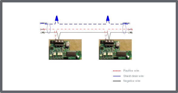
The REF terminal should never be used to wire shields. The two shields from each feed of the network connection to a thermostat should be wired together in the back of the thermostat and properly protected to prevent any accidental connection to the ground.
Review of the RS-485 interface provided on the network adapter yields the following interface attributes:
|
Transceiver |
Transceiver Unit Load |
Transceiver Failsafe |
Adapter Circuit Bias |
Circuit Bias Load |
Total Unit Load |
Isolated RS-485 Bus |
|
STM ST485C |
0.500 |
No |
100 kohm |
0.120 |
0.620 |
Yes |
Viconics recommends a data rate of 38.4 kbps for most systems and notes that the 76.8 kbps data rate is available for large networks (80+ devices). These rates call for the recommended use of End Of Line (EOL) resistor termination.
 RS-485 Communications
 Viconics VT/VZ/SE 7xxx Series Devices
 VT/VZ7xxx Configuration 2: Dual End-point Bias (External Supply Source)