Konzept
VT/VZ7xxx Configuration 1: Single End-point Bias (Automation Server Provided Source)
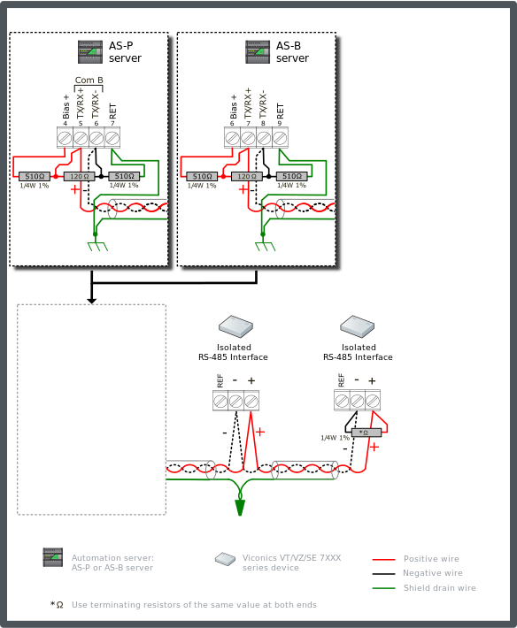
This configuration is the simplest to arrange and supports bus lengths out to 150 m (500 ft) on 24 AWG (0.20 mm²). The automation server should be configured with two 510 ohm bias resistors. One resistor connecting the + data line to the Bias+ terminal on the automation server and the other resistor connecting the – data line to the RET terminal on the automation server. The bias is required to support the transceivers in the VT/VZ nodes and the termination of the bus. AS-P servers and AS-B servers provide 5 V for bias, which supports 120 ohm termination resistors at the two ends of the bus. This will achieve the minimum idle line bias voltage of +200 mV required by the transceivers. Low resistance bias configurations (with 5 V supplies) add significant common mode load on the RS-485 network. The common mode load (Unit Load) of the bias network must be summed with the accumulated unit load of the collection of VT/VZ thermostats/controllers to identify the total unit load on the bus.
The requirement for bias resistors to maintain an idle state voltage greater than 200 mV also presents a limitation on the wire length due to idle state voltage drop produced by the wire resistance. The restricted length is due to the voltage divider network setup by the wire resistance and the termination resistance at the far end. See table below for recommended wire sizes and maximum distance. Configuration 2 offers a superior alternative option if long cable lengths are needed. Für weitere Informationen siehe VT/VZ7xxx Configuration 2: Dual End-point Bias (External Supply Source) .
Connect a 510 ohm bias resistor from the TX/RX+ terminal to the Bias+ terminal on the automation server (see the figure below). Connect another 510 ohm bias resistor from the TX/RX- terminal to the RET terminal on the automation server.
Connect a termination 120 ohm resistor across the + and - data lines at the head end of the bus (typically at the automation server). Connect another termination resistor across the + and - data lines on the last node at the far end of the bus.
Connect the shield drain wire to earth ground terminal rail in the panel with the automation server. This is the only ground connection of the shield for the complete cable segment. The shield drain wire from the cable segments are twisted together and passed by each node.
Use only twisted pair bus cable specified for use with RS-485 (for example, Belden 9841 or equivalent). Für weitere Informationen siehe Cable Selection .
The example diagram below shows the alternate RS-485 terminal block connections for the different automation server models.
The example diagram below shows the RS-485 Com B connections on the AS-P and AS-B servers. The guidelines are the same for Com A. When failsafe bias resistors are required on the Com A network, the pull-up voltage is obtained from the Bias+ terminal.

The recommended maximum cable length and associated wire sizes are listed in the following table. These wire size and lengths are selected to maintain the minimum idle state voltage at the far terminated end of the network (away from the automation server where the bias is provided).
|
Maximum Length |
Wire Size |
|
150 m (500 ft) |
24 AWG (0.20 mm²) |
|
240 m (800 ft) |
22 AWG (0.33 mm²) |
The maximum sensor/node count is 38 (using only the VT/VT7xxx devices). The node count reduces if mixed network with non-isolated devices (such as b3 BACnet devices). Node count discussions and other limiting factors are described separately. Für weitere Informationen siehe Expanded Unit Load with Network of Isolated Devices Only (Viconics VT/VZ7xxx Devices) .
 Viconics VT/VZ/SE 7xxx Series Devices
 VT/VZ7xxx Configurations
 VT/VZ7xxx Configuration 2: Dual End-point Bias (External Supply Source)
 Cable Selection
 Expanded Unit Load with Network of Isolated Devices Only (Viconics VT/VZ7xxx Devices)