Concepto
Legrand Configuration 1: Terminated Bus with No Bias Requirement
This configuration is recommended when using any combination of Legrand meter models 04677, 04680, and 04684. The configuration does not apply to the model 14669. The configuration uses 120 ohm End Of Line (EOL) termination resistors and requires no extra biasing.
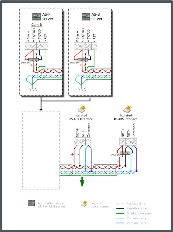
Connect a 120 ohm termination resistor across the + and - data lines at the head end of the bus (typically at the automation server). Connect another 120 ohm termination resistor across the + and - data lines on the last node at the far end of the bus.
Connect the two RS-485 common wire pair and the shield to earth ground terminal rail in the panel with the automation server. This is the only ground connection of the shield for these conductors. The shield drain wire from the cable segments are twisted together and passed by each node.
Both conductors of the second twisted pair cable are used to connect RS-485 Common on the meters.
Use only twisted pair bus cable specified for use with RS-485 (for example, Belden 9842 or equivalent). Para obtener más información, consulte Cable Selection (Legrand Power Meters) .
The example diagram below shows the alternate RS-485 terminal block connections for the different automation server models.
The example diagram below shows the RS-485 Com B connections on the AS-P and AS-B servers. The guidelines are the same for Com A.

In this configuration, the failsafe feature of the transceivers allows the full RS-485 cable length to be supported with 24 AWG (0.20 mm²) wire size without the node count and length reductions associated with failsafe bias load seen with Configuration 2, 3, and 4. Para obtener más información, consulte Legrand Configurations .
With products such as these three models using integrated failsafe transceivers, the addition of extra bias would typically only be applicable to system conditions prompting high levels of differential noise. In a well balanced cable system the differential noise is expected to be below 50 mV. With no added bias, the automation server will accommodate noise of approximately 130 mV pp or more. Additional biasing will typically not be needed. In a system with Legrand meters, significant additional biasing is being supplied internal to the meters. This is what elevates the Total Unit Load values. Para obtener más información, consulte General Legrand Power Meter Properties . For example, with 10 Legrand meters, the equivalent of a 1 kohm bias is accumulated on the bus. This alone increases the idle state line voltage by an additional 200 mV and presents an additional 12UL of load.
Each of the models 04677, 04680, and 04684 presents an RS-485 network load of 1.32UL. The automation server has a network load of 0.5UL. To determine the number of nodes (meters) the bus will support, we first determine the remaining available unit load capacity after subtracting the base load of the automation server. This configuration does not require bias which would present a large reduction.
For networks connecting only with Legrand meters, the initial unit load budget is 48UL. For networks with one or more other Modbus devices that are not isolated, the initial unit load budget is 32UL. Subtracting the automation server load of 0.5UL, we have a remaining capacity of 47.5UL (all isolated) or 31.5UL (mixed).
For isolated network, the calculated maximum node count is 47.5 / 1.325 = 35.8 nodes (meters).
For mixed network, the calculated maximum node count is 31.5 / 1.325 = 23.7 nodes (meters).
 Legrand Power Meters
 Legrand Configurations
 Legrand Configuration 2: Unterminated Bus with Minimal Bias
 Legrand Configuration 3: Terminated Bus with Single End-point Bias
 Legrand Configuration 4: Terminated Bus with Dual End-point Bias
 Cable Selection (Legrand Power Meters)
 General Legrand Power Meter Properties