Pojęcie
Legrand Configuration 3: Terminated Bus with Single End-point Bias
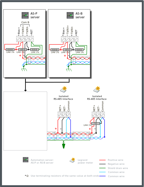
A third configuration option is available where low resistance bias is added to the automation server to allow termination to be applied on a network containing one or more model 14669 meters. The configuration applies to any combination of Legrand models 04677, 04680, 04684, or 14669. AS-P and AS-B servers provide a 5 V bias voltage supply, which supports 120 ohm termination resistors at the two ends of the bus.
Low resistance bias configurations (with 5 V) add significant common mode load on the network. The common mode load is a function of the bias resistor values and not the voltage. Maintaining the minimum +225 mV idle voltage on a terminated bus being biased from one end limits the network to shorter distances (for a specific wire gauge). This limitation is caused by the voltage divider network setup by the wire resistance and the termination resistance at the far end. Larger wire can be used to reach longer distances. See table below. Another option to achieve long distances is to bias the network from two ends, according to Configuration 4. Więcej informacji zawiera Legrand Configuration 4: Terminated Bus with Dual End-point Bias .
Connect a 510 ohm bias resistor from the TX/RX+ terminal to the Bias+ terminal on the automation server (see the figure below). Connect another 510 ohm bias resistor from the TX/RX- terminal to the RET terminal on the automation server.
Connect a 120 ohm termination resistor across the + and - data lines at the head end of the bus (typically at the automation server). Connect another termination resistor across the + and - data lines on the last node at the far end of the bus.
Connect the two RS-485 common wire pair and the shield to earth ground terminal rail in the panel with the automation server. This is the only ground connection of the shield for these conductors. The shield drain wire from the cable segments are twisted together and passed by each node.
Both conductors of the second twisted pair cable are used to connect RS-485 Common on the meters.
Use only twisted pair bus cable specified for use with RS-485 (for example, Belden 9842 or equivalent). Więcej informacji zawiera Cable Selection (Legrand Power Meters) .
The example diagram below shows the alternate RS-485 terminal block connections for the different automation server models.
The example diagram below shows the RS-485 Com B connections on the AS-P and AS-B servers. The guidelines are the same for Com A. When failsafe bias resistors are required on the Com A network, the pull-up voltage is obtained from the Bias+ terminal.

The recommended maximum cable length and associated wire sizes are listed in the following table. These wire size and lengths are selected to achieve compliant idle state voltage at the far end of the network.
|
Maximum Length |
Wire Size |
|
150 m (500 ft) |
24 AWG (0.20 mm²) |
|
240 m (800 ft) |
22 AWG (0.33 mm²) |
Each of the models 04677, 04680, and 04684 presents an RS-485 network load of 1.32UL, and the model 14669 has a network load of 1.75UL. The automation server has a network load of 0.5UL. To determine the number of nodes (meters) the bus will support, we first determine the remaining available unit load capacity after subtracting the base load of the automation server, and the load produced by the bias resistors.
For networks connecting only with Legrand meters, the initial unit load budget is 48UL. For networks with one or more other Modbus devices that are not isolated, the initial unit load budget is 32UL. The automation server has a unit load of 0.5UL. The 510 ohm bias gives a unit load of 23.5UL (12,000 / 510). Subtracting these two loads from the initial budget gives a remaining capacity of 24UL (all isolated) or 8UL (mixed).
For isolated network, the calculated maximum node count is:
For models 04677, 04680, and 04684: 24 / 1.325 = 18.1 nodes (meters)
For model 14669: 24 / 1.75 = 13.7 nodes (meters)
For mixed network, the calculated maximum node count is:
For models 04677, 04680, and 04684: 8 / 1.325 = 6 nodes (meters)
For model 14669: 8 / 1.75 = 4.5 nodes (meters)
You can accommodate the load from a mixed combination of model 14669 meters and the others by simply summing their individual Total Unit Load values. Więcej informacji zawiera General Legrand Power Meter Properties . The maximum recommended limit is reached when that sum reaches 24UL (for all isolated) or 8UL (for mixed network).
 Legrand Power Meters
 Legrand Configurations
 Legrand Configuration 4: Terminated Bus with Dual End-point Bias
 Cable Selection (Legrand Power Meters)
 General Legrand Power Meter Properties