Concepto
Legrand Configuration 2: Unterminated Bus with Minimal Bias
This configuration uses no bus termination, which means reduced data rates and cable lengths. The configuration applies to any combination of Legrand meter models 04677, 04680, 04684, or 14669.
When using any combination of Legrand models that include the model 14669 (with the 14673 RS-485 optional plug-in), Configuration 1 cannot be used. Para obtener más información, consulte Legrand Configuration 1: Terminated Bus with No Bias Requirement . The transceiver in the 14673 module requires a minimum of +200 mV idle line voltage (plus 25-50 mV for noise margin) to insure a known idle state data output when no transmitters are active. Bias resistors must be added to the bus to pull the + and – lines apart. To minimize load on the bus (lowering node count), higher resistance values are preferred. However, a high resistance bias will not work if bus termination must be applied. Configuration 2 omits the use of termination. With data rates of 19,200 bps and lower, and cable lengths of less than 150 m (500 ft), the reflections from an unterminated bus can be tolerated. Without the 120 ohm resistors at the ends of the bus, the differential signal voltage will expand to wider level allowing higher noise immunity during the idle state.
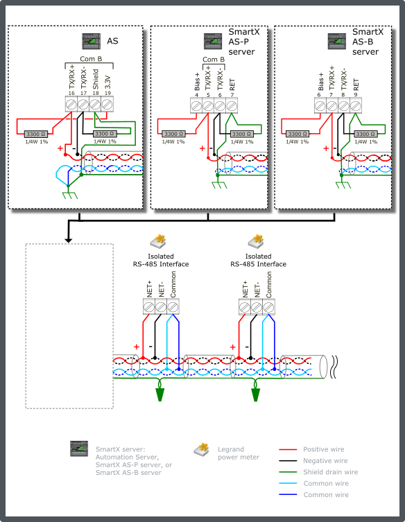
Connect a 3300 ohm bias resistor from the TX/RX+ terminal to the Bias+/3.3V terminal on the SmartX server (see the figure below). Connect another 3300 ohm bias resistor from the TX/RX- terminal to the RET/Shield terminal on the SmartX server.
Connect the two RS-485 common wire pair and the shield to earth ground terminal rail in the panel with the SmartX server. This is the only ground connection of the shield for these conductors. The shield drain wire from the cable segments are twisted together and passed by each node.
Both conductors of the second twisted pair cable are used to connect RS-485 Common on the meters.
Use only twisted pair bus cable specified for use with RS-485 (for example, Belden 9842 or equivalent). Para obtener más información, consulte Cable Selection (Legrand Power Meters) .
The example diagram below shows the alternate RS-485 terminal block connections for the different SmartX server models.
The example diagram below shows the RS-485 Com B connections on the Automation Server, SmartX AS-P servers, and SmartX AS-B servers. The guidelines are the same for Com A. When failsafe bias resistors are required on the Com A network, the pull-up voltage is obtained from the 3.3V/Bias+ terminal.

In Configuration 2, the SmartX server is connected with 3.3 kohm failsafe bias resistors. These resistors pull the + and – data lines apart during an idle bus period. Without the termination resistors, this configuration will easily achieve the minimum +225 mV level for the full length of the bus. The 3.3 kohm bias serves to override the faulty bias influence from a Legrand meter when one or more of the meters lose power while they are still connected to the bus. The TIA-485A specification on transceivers requires that they do not place any additional load on the bus when they lose power. The addition of bias resistors within individual RS-485 network products compromises that insulation from power loss affects. Lower bias resistance values generate higher levels of bias current and produce more ill effect from a power down situation.
Each of the models 04677, 04680, and 04684 presents an RS-485 network load of 1.32UL, and the model 14669 has a network load of 1.75UL. The SmartX server has a network load of 0.5UL. To determine the number of nodes (meters) the bus will support, we first determine the remaining available unit load capacity after subtracting the base load of the SmartX server, and the load produced by the bias resistors.
For networks connecting only with Legrand meters, the initial unit load budget is 48UL. For networks with one or more other Modbus devices that are not isolated, the initial unit load budget is 32UL. The SmartX server has a unit load of 0.5UL. The 3.3 kohm bias gives a unit load of 3.63UL (12,000 / 3,300). Subtracting these two loads from the initial budget gives a remaining capacity of 43.8UL (all isolated) or 27.8UL (mixed).
For isolated network, the calculated maximum node count is:
For models 04677, 04680, and 04684: 43.8 / 1.325 = 33 nodes (meters)
For model 14669: 43.8 / 1.75 = 25 nodes (meters)
For mixed network, the calculated maximum node count is:
For models 04677, 04680, and 04684: 27.8 / 1.325 = 20.9 nodes (meters)
For model 14669: 27.8 / 1.75 = 15.7 nodes (meters)
You can accommodate the load from a mixed combination of model 14669 meters and the others by simply summing their individual Total Unit Load values. Para obtener más información, consulte General Legrand Power Meter Properties . The maximum recommended limit is reached when that sum reaches 43.8 (for all isolated) or 27.87UL (for mixed network).
 Legrand Power Meters
 Legrand Configurations
 Legrand Configuration 1: Terminated Bus with No Bias Requirement
 Cable Selection (Legrand Power Meters)
 General Legrand Power Meter Properties