Concepto
Generic RS-485 Network Device Configuration 2
This configuration is recommended if the following conditions apply to the RS-485 network devices to be connected to the automation server's RS-485 port:
All RS-485 network devices have failsafe receivers.
All RS-485 network devices have isolated RS-485 interfaces.
If all the devices being connected to the automation server's RS-485 port provide failsafe receivers, the configuration becomes very simple and no node or distance reductions are called for. The failsafe receivers can typically operate with no added bias resistors.
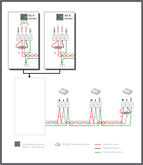
Connect a 120 ohm termination resistor across the + and - data lines at the head end of the bus (typically at the automation server). Connect another 120 ohm termination resistor across the + and - data lines on the last node at the far end of the bus.
Connect the shield drain wire to earth ground terminal rail in the panel with the automation server. This is the only ground connection of the shield for the complete cable segment. Connect the RET terminal (see the figure below) on the automation server to the ground rail in the panel using a 12 AWG (3.31 mm²) to 18 AWG (0.82 mm²) wire.
The shield drain wires from the cable segments are connected to the RS-485 reference/common terminal at each RS-485 network device.
The example diagram below shows the alternate RS-485 terminal block connections for the different automation server models.
The example diagram below shows the RS-485 Com B connections on the AS-P and AS-B servers. The guidelines are the same for Com A.

The unit load rating will determine the recommended maximum number of nodes you should install on this copper segment. Select the higher unit load value between answers Q5 and Q6B. Para obtener más información, consulte Worksheet for Configuration of RS-485 Bus with Generic RS-485 Devices . If all devices on the bus segment are isolated RS-485 interfaces (except the automation server), it is recommended that we can boost the starting unit load budget from 32UL to 48UL. This extra UL capacity is related to the fact that the isolated interfaces provide an avoidance of Common Mode Voltage. Para obtener más información, consulte Expanded Unit Load with Network of Isolated Devices Only (MNB and Generic RS-485 Devices) . Subtracting the automation server unit load of 0.5 leaves 47.5 for the isolated RS-485 nodes. Divide 47.5 by the UL value (from Q5 or Q6b). The result is the maximum recommended node count in regards to bus loading.
If the answer to Q5 is 1.0 and the answer to Q6b is 1.25, use the value 1.25. Calculate the maximum recommended node count as 47.5 / 1.25 = 38 nodes. It is recommended that you use the calculated 38 node maximum limit instead of the 47.5 node value suggested by the 1.0 UL published UL load rating. It is likely that the node has added bias resistors that are not considered in the 1.0 published value.
The recommended limits on RS-485 bus node counts discussed here pertain to hardware bias and unit load considerations only. The recommended maximum node count may be further limited based on product and system version.
For this terminated configuration with no biasing, the maximum cable length may extend to the full standard length of 1200 m (4000 ft).
 Generic RS-485 Network Devices
 Configuration Selection for Generic RS-485 Network Devices
 Worksheet for Configuration of RS-485 Bus with Generic RS-485 Devices
 Expanded Unit Load with Network of Isolated Devices Only (MNB and Generic RS-485 Devices)