
Concepto
Universal Inputs/Outputs
The universal inputs/outputs are ideal for any mix of temperature, pressure, flow, status points, and similar point types in a building control system.
As counter inputs, the universal inputs/outputs are commonly used in energy metering applications. As RTD inputs, they are ideal for temperature points in a building control system. As supervised inputs, they are used for security applications where it is critical to know whether or not a wire has been cut or shorted. These events provide a separate indication of alarms and trouble conditions to the system.
The universal inputs/outputs are capable of supporting analog outputs of type voltage outputs. Therefore, the universal inputs/outputs support a wide range of devices, such as actuators.
The AS-B's universal inputs/outputs consist of two types: Ua and Ub. The difference between the two types of universal inputs/outputs is that the Ub type supports current inputs.
Inputs
The universal inputs/outputs can be configured to read several different types of inputs:
Digital
Counter
Supervised
Voltage
Current (Ub only)
Temperature
Resistive
2-Wire RTD temperature
2-Wire RTD resistive

Applied voltages beyond the absolute maximum ratings will cause over current in the protection component D Z .
The external connection of a digital input is shown in the following figure.

K is the monitored external switch.
V S = 24 V
R PU = 10 kohm
A counter input utilizes the same hardware configuration as the digital input as shown in the figure above.
Supervised inputs are contact closing inputs supplemented with the supervision of the field wiring integrity. This supervision is a required feature in many security system applications. The supervised inputs provide the ability to detect specific forms of tampering or trouble with the wire connections to the field contacts. The supervision is achieved with a combination of 1 or 2 resistors attached to the contact in the field. The resistor combination creates continuous current flow through the field contact loop and presents a defined set of expected resistance values for each of the defined conditions. If someone is attempting to defeat the monitoring of the field contact by short circuiting the wire with a jumper or cutting the wire, the objective is to detect and indicate such a condition. The resistors need to be located at the end of the cable close to the field contact, so that the point where there is a risk that the circuit is defeated is between the resistors and the I/O.
Three different types of supervised input connections are supported:
Series only
Parallel only
Series and parallel
Each type of supervised input connection provides a different capability in regards to what form of tamper/trouble can be detected regardless of switch contact open or closed condition.
A single resistor, which is connected in series with the switch, can only detect tamper/trouble in the form of a short circuit across the wire pair. The external connection of a series only supervised input connection is shown in the following figure.
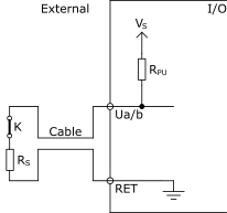
K is the monitored external switch.
V S = 5 V
R PU = 10 kohm
A single resistor, which is connected in parallel with the switch, can only detect tamper/trouble in the form of an open circuit in the field wiring loop. The external connection of a parallel only supervised input connection is shown in the following figure.

K is the monitored external switch.
V S = 5 V
R PU = 10 kohm
Two resistors, where one is connected in series with the switch and one is connected in parallel with the switch, can detect tamper/trouble conditions in the form of both an open and a shorted circuit. The external connection of a series and parallel supervised input connection is shown in the following figure.
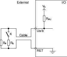
K is the monitored external switch.
V S = 5 V
R PU = 10 kohm
The external connection of a voltage input is shown in the following figure.
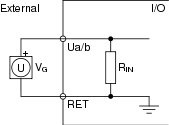
V G is the monitored external voltage.
R IN = 100 kohm
The external connection of a current input is shown in the following figure.

I G is the monitored external current.
R SH = 47 ohm
In the internal configuration of the current input, there is a current limit circuit in order to protect the shunt resistor from over load. The input current is limited to 60 mA with a serial connected FET transistor. If this limit is reached for 0.5 s, the transistor is turned off. When 5 s has elapsed, the transistor is turned on again to make a new start attempt.
The external connection of a temperature input is shown in the following figure.
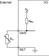
R T is the monitored external thermistor.
When a universal input is used as a temperature input, V S and R PU in the internal configuration of the universal input are used according to the following table.
|
Thermistor type |
V S |
R PU |
|
20 kohm |
5 V |
10 kohm |
|
10 kohm |
5 V |
10 kohm |
|
2.2 kohm |
1 V |
1.5 kohm |
|
1.8 kohm |
1 V |
1.5 kohm |
|
1 kohm |
1 V |
1.5 kohm |
The resulting voltage across the thermistor is measured and a temperature is calculated dependent on the selected thermistor type.
The external connection of a resistive input is shown in the following figure.
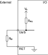
R M is the monitored external resistance.
V S = 5 V
R PU = 10 kohm
The external connection of a 2-wire RTD temperature input is shown in the following figure.

R T is the monitored external RTD.
R W is the wiring resistance.
V S = 1 V
R PU = 1.5 kohm
When an input is used as a 2-wire RTD temperature input, you need to state the wiring resistance in the software.
The resulting voltage across the RTD is measured, and the temperature is calculated dependent on the selected RTD type.
The external connection of a 2-wire RTD resistive input is shown in the following figure.

R T is the monitored external resistance.
R W is the wiring resistance.
V S = 1 V
R PU = 1.5 kohm
When an input is used as a 2-wire RTD resistive input, you need to state the wiring resistance in the software.
The resulting voltage across the RTD is measured, and the resistance is calculated dependent on the selected RTD type.
The RTD resistive input type is used to measure the resistance of an RTD other than the supported types. The resistance to temperature conversion must be performed in a function block or script program in the device.
Outputs
The universal inputs/outputs can be configured as voltage outputs.
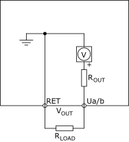
R OUT is approximately equal to 10 ohm.
Especificaciones
Channels, AS-B with 24 I/O points
|
12 Ua, Ua1–Ua12
|
4 Ub, Ub1–Ub4
|
|
Channels, AS-B with 36 I/O points
|
20 Ua, Ua1–Ua20,
|
8 Ub, Ub1–Ub8
|
|
Absolute maximum ratings
|
-0.5 to +24 VDC
|
A/D converter resolution
|
16 bits
|
| Digital inputs | |
Range
|
Dry contact switch closure or open collector/open drain, 24 VDC, typical wetting current 2.4 mA
|
Minimum pulse width
|
120 ms
|
| Counter inputs | |
Range
|
Dry contact switch closure or open collector/open drain, 24 VDC, typical wetting current 2.4 mA
|
Minimum pulse width
|
20 ms
|
Maximum frequency
|
25 Hz
|
| Supervised inputs | |
| 5 V circuit, 1 or 2 resistors | |
| Monitored switch combinations | Series only, parallel only, and series and parallel
|
Resistor range
|
1 to 10 kohm
|
| For a 2-resistor configuration, each resistor is assumed to have the same value +/- 5 % | |
| Voltage inputs | |
Range
|
0 to 10 VDC
|
Accuracy
|
+/-(7 mV + 0.2 % of reading)
|
Resolution
|
0.5 mV
|
Impedance
|
100 kohm
|
Reliability check
|
Yes
|
| Current inputs | |
Range
|
0 to 20 mA
|
Accuracy
|
+/-(0.01 mA + 0.4 % of reading)
|
Resolution
|
1 μA
|
Impedance
|
47 ohm
|
Reliability check
|
Yes
|
| Resistive inputs | |
10 ohm to 10 kohm accuracy
|
+/-(7 + 4 x 10
-3
x R) ohm
|
| R = Resistance in ohm | |
10 kohm to 60 kohm accuracy
|
+/-(4 x 10
-3
x R + 7 x 10
-8
x R
2
) ohm
|
| R = Resistance in ohm | |
Reliability check
|
Yes
|
| Temperature inputs (thermistors) | |
Range
|
-50 to +150 °C (-58 to +302 °F)
|
Reliability check
|
Yes
|
| Supported thermistors | |
Honeywell
|
20 kohm
|
Type I (Continuum)
|
10 kohm
|
Type II (I/NET)
|
10 kohm
|
Type III (Satchwell)
|
10 kohm
|
Type IV (FD)
|
10 kohm
|
Type V (FD w/ 11k shunt)
|
Linearized 10 kohm
|
Satchwell D?T
|
Linearized 10 kohm
|
Johnson Controls
|
2.2 kohm
|
Xenta
|
1.8 kohm
|
Balco
|
1 kohm
|
| Thermistor accuracy | |
20 kohm
|
-50 to -30 °C: +/-1.5 °C (-58 to -22 °F: +/-2.7 °F)
|
-30 to 0 °C: +/-0.5 °C (-22 to +32 °F: +/-0.9 °F)
|
|
0 to 100 °C: +/-0.2 °C (32 to 212 °F: +/-0.4 °F)
|
|
100 to 150 °C: +/-0.5 °C (212 to 302 °F: +/-0.9 °F)
|
|
10 kohm, 2.2 kohm, and 1.8 kohm
|
-50 to -30 °C: +/-0.75 °C (-58 to -22 °F: +/-1.35 °F)
|
-30 to +100 °C: +/-0.2 °C (-22 to +212 °F: +/-0.4 °F)
|
|
100 to 150 °C: +/-0.5 °C (212 to 302 °F: +/-0.9 °F)
|
|
Linearized 10 kohm
|
-50 to -30 °C: +/-2.0 °C (-58 to -22 °F: +/-3.6 °F)
|
-30 to 0 °C: +/-0.75 °C (-22 to +32 °F: +/-1.35 °F)
|
|
0 to 100 °C: +/-0.2 °C (32 to 212 °F: +/-0.4 °F)
|
|
100 to 150 °C: +/-0.5 °C (212 to 302 °F: +/-0.9 °F)
|
|
1 kohm
|
-50 to +150 °C: +/-1.0 °C (-58 to +302° F: +/-1.8 °F)
|
| RTD temperature | |
Reliability check
|
Yes
|
Supported RTDs
|
Pt1000, Ni1000, and LG-Ni1000
|
| Pt1000 | |
Range
|
-50 to +150 °C (-58 to +302 °F)
|
Accuracy
|
-50 to +70 °C: +/-0.5 °C (-58 to +158 °F: +/-0.9 °F)
|
70 to 150 °C: +/-0.7 °C (158 to 302 °F: +/-1.3 °F)
|
|
| Ni1000 | |
Range
|
-50 to +150 °C (-58 to +302 °F)
|
Accuracy
|
+/-0.5 °C (+/-0.9 °F)
|
| LG-Ni1000 | |
Range
|
-50 to +150 °C (-58 to +302 °F)
|
Accuracy
|
+/-0.5 °C (+/-0.9 °F)
|
| RTD temperature wiring | |
Maximum wire resistance
|
20 ohm/wire (40 ohm total)
|
Maximum wire capacitance
|
60 nF
|
| The wire resistance and capacitance typically corresponds to a 200 m wire. | |
| RTD resistive | |
Reliability check
|
Yes
|
| 1,000 ohm | |
Range
|
500 to 2,200 ohm
|
Including wiring resistance
|
|
Accuracy
|
+/-(0.2 + 1.5 x 10
-3
x R) ohm
|
| R = resistance in ohm | |
Resolution
|
0.1 ohm
|
| RTD resistive wiring | |
Maximum wire capacitance
|
60 nF
|
| Voltage outputs | |
Range
|
0 to 10 VDC
|
Accuracy
|
+/-60 mV
|
Resolution
|
10 mV
|
Minimum load resistance
|
5 kohm
|
Load range
|
-1 to +2 mA
|
 AS-Bs
AS-Bs
 AS-B Onboard I/O