Концепт
MP-C Controller LEDs
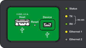
There are five or three LEDs on the front panel of the MP-C controller, depending on the MP-C model.
MP-C controller models with “-M” in the product name do not have Ethernet ports with associated LEDs. These MP-C models only have three LEDs: Status, RS-485 Tx, and RS-485 Rx. Более подробную информацию см. MP-C Models .

|
Function |
Color |
|
Status (MP-C controller) |
Green/Red |
|
RS-485 Tx |
Yellow |
|
RS-485 Rx |
Green |
|
Ethernet 1 |
Green/Yellow |
|
Ethernet 2 |
Green/Yellow |
The MP-C controller Ethernet and Status indicators comprise two LEDs (green/yellow and green/red respectively) in one structure.
The LEDs indicate status of the MP-C controller and the ongoing communication.
Status LED
The MP-C controller Status LED indicates the condition of the device.
|
LED Patterns |
Condition |
|
Green, constant |
Normal operation, status OK MP-C controller firmware application running |
|
Green, flashing (~1 Hz) |
Device restarting, wait MP-C controller firmware application running |
|
Red, constant |
Detected error, attention required |
|
Red, flashing (~1 Hz) |
Device operates, but a problem needs attention |
|
Red/green, flashing (~1 Hz) |
MP-C controller I/O board receiving software upgrade, wait Do not interrupt power to the controller. For more information, see the following Important note. |
|
Amber, constant |
MP-C controller firmware boot applet running |
|
Amber, flash |
Device restarting, wait MP-C controller firmware boot applet started |
|
Amber/green, flashing (~1 Hz) |
MP-C controller firmware is being upgraded. It is typically the firmware main application, but it can also be a boot applet. |
Avoid power interruptions to the device during the brief period when the Status LED is flashing red and green. An interruption causes problems with the I/O processor upgrade and can result in corrupt firmware. You can view the evidence of a corrupt processor when the device reports itself as an “MP-C-15A.” A corrupt I/O processor can lead to the loss of the reset button and/or I/O functionality, as well as the inability to upgrade the I/O processor and/or the device.
RS-485 LEDs
The RS-485 LEDs indicate the condition of the RS-485 network data communication.
The labeling of the RS-485 LEDs differs between different versions of the MP-C controller models. In previous versions, the LEDs are labeled “Sensor Bus”.
|
LED Patterns |
Condition |
|
Yellow, flashing (Tx) |
Transmit data |
|
Green, flashing (Rx) |
Receive data |
Ethernet LEDs
The Ethernet (1 and 2) LEDs indicate the condition of the Ethernet communication.
|
LED Patterns |
Condition |
|
Green, flashing |
10 Mbit communication |
|
Yellow, flashing |
100 Mbit communication |
|
Green/yellow, constant |
10/100 Mbit link connected, no activity |
|
No light |
No link, no activity |
 MP-C Controllers
 MP-C Models
 Status LEDs