Concept
Screw Terminals for AS-Bs with 24 I/O Points
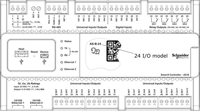
AS-Bs with 24 I/O points use nine pluggable terminal blocks and one fixed terminal block.
The terminal blocks are used as follows:
One 3-position pluggable terminal block for the power input
One 2-position fixed terminal block for the two return terminals
One 4-position pluggable terminal block for RS-485 communication
One 6-position pluggable terminal block for the four universal inputs/outputs of type Ub
One 6-position pluggable terminal block for the four digital inputs
One 8-position pluggable terminal block for the four relay outputs
Four 6-position pluggable terminal blocks for the 12 universal inputs/outputs of type Ua
The following figure shows the screw terminals of an AS-B with 24 I/O points.

The following table describes the screw terminals of an AS-B with 24 I/O points.
|
Terminal number |
Designation |
Usage |
|
Power input |
|
|
|
1 |
L/+ |
Line (L) lead when operating the device from 24 VAC, 50/60 Hz, 15 VA Positive (+) lead when operating the device from 24-30 VDC, 10 W |
|
2 |
N/– |
Neutral (N) lead when operating the device from 24 VAC, 50/60 Hz, 15 VA Negative (–) lead when operating the device from 24-30 VDC, 10 W |
|
3 |

|
Earth ground |
|
Return terminals |
|
|
|
4 |
RET |
Internally connected to ground |
|
5 |
RET |
Internally connected to ground |
|
RS-485 |
|
|
|
6 |
Bias + |
5.0 VDC, RS-485 bias supply, current limited 40 mA |
|
7 |
TX/RX + |
RS-485 communication |
|
8 |
TX/RX – |
RS-485 communication |
|
9 |
RET |
Internally connected to ground |
|
Universal inputs/outputs |
|
|
|
10 |
Ub1 |
Universal input/output, type Ub |
|
11 |
RET |
Internally connected to ground |
|
12 |
Ub2 |
Universal input/output, type Ub |
|
13 |
Ub3 |
Universal input/output, type Ub |
|
14 |
RET |
Internally connected to ground |
|
15 |
Ub4 |
Universal input/output, type Ub |
|
Digital inputs |
|
|
|
16 |
DI1 |
Digital input |
|
17 |
RET |
Internally connected to ground |
|
18 |
DI2 |
Digital input |
|
19 |
DI3 |
Digital input |
|
20 |
RET |
Internally connected to ground |
|
21 |
DI4 |
Digital input |
|
Relay outputs |
|
|
|
22 |
DO1 |
Relay output, type Form A |
|
23 |
DO1 |
Relay output, type Form A |
|
24 |
DO2 |
Relay output, type Form A |
|
25 |
DO2 |
Relay output, type Form A |
|
26 |
DO3 |
Relay output, type Form A |
|
27 |
DO3 |
Relay output, type Form A |
|
28 |
DO4 |
Relay output, type Form A |
|
29 |
DO4 |
Relay output, type Form A |
|
Universal inputs/outputs, type Ua |
|
|
|
30 |
RET |
Internally connected to ground |
|
31 |
Ua1 |
Universal input/output, type Ua |
|
32 |
RET |
Internally connected to ground |
|
33 |
Ua2 |
Universal input/output, type Ua |
|
34 |
RET |
Internally connected to ground |
|
35 |
Ua3 |
Universal input/output, type Ua |
|
36 |
RET |
Internally connected to ground |
|
37 |
Ua4 |
Universal input/output, type Ua |
|
38 |
RET |
Internally connected to ground |
|
39 |
Ua5 |
Universal input/output, type Ua |
|
40 |
RET |
Internally connected to ground |
|
41 |
Ua6 |
Universal input/output, type Ua |
|
42 |
RET |
Internally connected to ground |
|
43 |
Ua7 |
Universal input/output, type Ua |
|
44 |
RET |
Internally connected to ground |
|
45 |
Ua8 |
Universal input/output, type Ua |
|
46 |
RET |
Internally connected to ground |
|
47 |
Ua9 |
Universal input/output, type Ua |
|
48 |
RET |
Internally connected to ground |
|
49 |
Ua10 |
Universal input/output, type Ua |
|
50 |
RET |
Internally connected to ground |
|
51 |
Ua11 |
Universal input/output, type Ua |
|
52 |
RET |
Internally connected to ground |
|
53 |
Ua12 |
Universal input/output, type Ua |
The screw terminals 6 to 9, intended for RS-485 communication, act as connectors to AS-B and are easily inserted/removed without disrupting the network. Doing so may help in isolating possible RS-485 communication problems.
 AS-Bs
AS-Bs
 AS-B Screw Terminals
 Wiring