How to
Connecting SpaceLogic Sensor Devices to an RP Controller
You connect SpaceLogic Sensor devices to an RP controller to provide the devices with power and communication from the controller.
Install the SpaceLogic Sensor and connect a Cat 5 (or higher) unshielded, straight-through wired cable with eight conductors (four twisted pairs) to one of the two RJ45 receptacles on the sensor. Use a cable with the wire size (cross-sectional area) 22 to 26 AWG (0.34 to 0.14 mm²).
For more information, see SpaceLogic Sensors - SXWS Sensor Base - Installation Instructions .
For more information, see SpaceLogic Sensors - SXWS LCD Temperature Sensors - Installation Instructions .
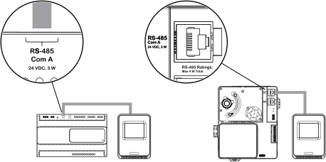
Connect the other end of the cable to the RP controller's RS-485 port that is configured for the sensor bus.
Note:By default, the RS-485 Com A port is configured for the sensor bus.
action_zoom_plus_stroke 
When an additional SpaceLogic Sensor is needed, install the sensor and connect the other end of the cable to the unused RJ45 receptacle on the previous sensor.
Note:When connecting SpaceLogic Sensor devices to the sensor bus through a daisy-chain configuration, the sensor bus ports on the SpaceLogic Sensor are interchangeable.
action_zoom_plus_stroke 
Repeat step 3 to install a third and fourth SpaceLogic Sensor.
Ensure that the two 2-position address DIP switches on each SpaceLogic Sensor are configured to give the sensor a unique address on the sensor bus.
For more information, see SpaceLogic Sensors - SXWS Sensor Base - Installation Instructions .
For more information, see SpaceLogic Sensors - SXWS LCD Temperature Sensors - Installation Instructions .
For more information, see Configuring a SpaceLogic Sensor .
 RP-C Controllers
 RP-V Controllers
 RP-C Sensor Bus
 RP-V Sensor Bus
 RP-C Communication Ports
 Communication Ports on RP-C Models with “-F” in the Product Name
 RP-V Communication Ports
 SpaceLogic Sensor or RP Controller Sensor Bus Is Not Operational
 Configuring a SpaceLogic Sensor


