Concepto
24 VAC Output on RP-C 230 V Controller Models
The RP-C 230 V controller models RP-C-16A-F-230V and RP-C-16B-F-230V have a 24 VAC (19 VA) Class 2 output that can be used to power external loads such as actuators, relays, or indicators. The external loads can be controlled using the controller's solid-state relay (SSR) or relay outputs.
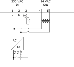
The RP-C 230 V controller models ( Para obtener más información, consulte RP-C Models .) use the internal transformer to convert 230 VAC from the power input (terminals 1 and 2) to 24 VAC (terminals 4 and 5). The transformer provides galvanic isolation between the 24 VAC output and the 230 VAC power input as well as the controller electronics, as shown in the following figure.
Screw terminal number 3 differs between different hardware versions of the controller model RP-C-16A-F-230V. Para obtener más información, consulte Differences Between RP-C Hardware Versions .

The output voltage varies linearly with the load connected to the 24 VAC output and the voltage from the power supply unit connected to the 230 VAC input.
With maximum load (19 VA ± 10 %), the output voltage is 22 VAC ± 10 % for the power supply voltage range 230 VAC ± 10 %
With no load, the output voltage is 28 VAC ± 10 % for the power supply voltage range 230 VAC ± 10 %
For example, when the power supply voltage is 230 VAC, the output voltage is approximately 28 VAC at no load, 24 VAC at 13 VA load, and 22 VAC at maximum load (19 VA). When the power supply voltage is 253 VAC and there is no load, the output voltage increases to the maximum value of 30.8 VAC. When the power supply voltage is 207 VAC and the load is at maximum, the output voltage drops to the minimum value of 19.8 VAC.
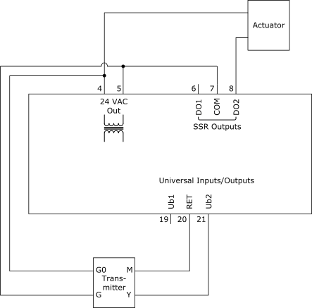
The following wiring example shows how an actuator can be connected to the controller's 24 VAC output and one of the SSR outputs. The example also shows how the 24 VAC output terminals 4 and 5 are connected to terminals G0 and G on a transmitter, for which the terminal M is connected to one of the RET terminals of the controller's Universal Inputs/Outputs. G0 and M of the transmitter may be interconnected internally or by a separate wire, which can introduce disturbances. Sometimes there is only one common ground connection G0/M, and this node must be connected to one of the 24 VAC output terminals and to a RET terminal. In the example below, the transmitter can be replaced by a voltage controlled actuator.

The polarity of the 24 VAC output terminals 4 and 5 is unknown, which means that the phase of the output relative to the input of the transformer is also unknown. For example, if you interconnect terminals 4 of two different controllers, a phase difference can result in a voltage difference of 0 VAC to 48 VAC between terminals 5 of the controllers. The primary side of the transformer has a PTC thermistor, which acts as a resettable fuse and turns off the voltage to the transformer in case of over current on the secondary side. However, the PTC thermistor does not provide any protection for external equipment from being exposed to 48 VAC.
In case the power 19 VA provided by the internal transformer is not sufficient for the actual application, an external transformer can be used instead of the internal transformer. It is also possible to use both at the same time, and to connect one pole on the internal transformer to one pole on the external transformer to be used as a common G0, but transformer outputs should never be connected in parallel. This applies to the internal RP-C transformer. If the consequences of this are not entirely clear, avoid using more than one transformer.
 Hardware Overview
 RP-C Controllers
 RP-C Models
 Differences Between RP-C Hardware Versions
 Peligro