earth_america
user_standard Iniciar sesión
action_search_stroke
earth_america
Log on to rate and give feedback 1 2 3 4 5 Log on to rate
0
Explicación de procesos

Explicación de procesos


Productos RP-C, RP-C-EXT-0-10V-4-PD, RP-C-EXT-BL-2-LV-PD, RP-C-EXT-BL-4-HV-PD, RP-C-EXT-DALI-M-PD
Funcionalidades: Hardware
Versión del producto: 3.1, 3.2
19/12/2019

Removing an External Connector from an RP Series Expansion Module

You remove an external connector from an RP Series expansion module to disconnect lights, blinds, dry contact digital inputs, or AC power from the module.

Mostrar más
action_close

The RP Series expansion modules have PCB mounted connectors for the power input, outputs and digital inputs. The connectors are mechanically keyed and color-coded, which allows the matching external connectors to be plugged in on site quickly and easily.

The pluggable connectors mean time savings and cost reductions for the installation, compared to wiring terminal blocks on site. The connectors can quickly and easily be plugged together on site.

The RP Series expansion modules use 2, 3, 4 or 5 pole connectors for the different inputs and outputs. The 4-pole connector has a 5-pole frame.

The connectors are mechanically keyed, which means the following connections cannot be made:

  • A connector for AC mains and high-voltage applications cannot be plugged into a connector for low-voltage applications.

  • A connector for low-voltage applications cannot be plugged into a connector for AC mains and high-voltage applications.

The matching connectors are locked together.

The connectors are also color-coded to help the installers and electricians to choose the correct, matching external connector. The connectors are color-coded:

  • Black: For AC mains power applications such as power supply input, blind high-voltage outputs, SMI (HV) blind outputs, and relay outputs.

  • Pastel blue: For dimming applications such as DALI light outputs and 0-10V light outputs with power distribution.

  • Light blue: For low-voltage applications such as blind low-voltage outputs (24 VDC), 0-10V light outputs without power distribution, SMI LoVo (LV) blind outputs, and digital inputs (5 VDC).

 
action_zoom_plus_stroke Color-coded connectors (example)
Figura: Color-coded connectors (example)

The matching external connectors are not provided but need to be ordered separately from Schneider Electric. Para obtener más información, consulte Required External Connectors for the RP Series Expansion Modules .

To remove an external connector from an RP Series expansion module
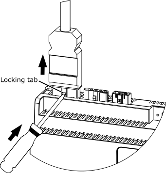
  1. Use a small screwdriver to press and hold down the connector locking tab and then gently pull the external connector until the tab is released from the locking latch (slot).

     
    action_zoom_plus_stroke
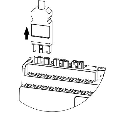
  2. Pull the external connector straight away from the mating connector.

     
    action_zoom_plus_stroke
  • RP Series Expansion Module Pluggable Connectors
  • Plugging an External Connector into an RP Series Expansion Module
  • Required External Connectors for the RP Series Expansion Modules
  • RP Series Expansion Module Device Installation