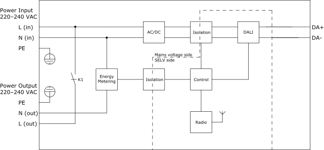
Concept
Zigbee DALI Light Output and Power Output
The Zigbee DALI module has one DALI light output for control of lights with electronic ballasts, LED drivers, and other control gear with DALI interface and one power output for power distribution to the control gear.
The Zigbee DALI module supports:
DALI lighting control
Power distribution (220–240 VAC)

The DALI light output equals one logical DALI channel.
The DALI light output has two screw terminals for DALI lighting control:
DA+
DA-
These two screw terminals are where the wires from the DALI bus are connected. The DALI bus is a 2-wire bus, which is used for bi-directional communication. For more information, see Wire Sizes and Lengths .
The Zigbee DALI module monitors and controls all control gear devices on the DALI bus. A broadcast address is used when communicating with the control gear devices on the bus. For example, a broadcast command can be used to change all LED drivers in a room from Off to On.
Up to 20 DALI control gear devices to can be connected to the Zigbee DALI module. The maximum number of control gear devices per module is also determined by the module's power distribution limitations. For more information, see section “Specifications”.
The power distribution capability means that the module distributes the AC mains voltage (220–240 VAC) from the Power Input to the control gear connected to the Power Output. For more information, see Zigbee Modules Power Distribution .
The Power Output has three screw terminals for power distribution:
- – Protective earth ground
action_zoom_plus_stroke 
N (out) – Neutral
L (out) – Line
The module uses a relay to control the power distribution, by connecting or disconnecting the AC mains voltage to the Power Output's L (out) terminal. In the figure above, the relay is named K1.
The module's AC mains voltage side and low-voltage side (SELV side) are galvanically separated by means of isolation circuitry.
The module has energy metering circuitry to measure the energy consumption for the total load connected to the module. For more information, see Zigbee Modules Power Consumption Monitoring .
Specifications
| DALI light output | |
Outputs
|
1 (1 DALI channel), terminals DA+ and DA-
|
DALI bus voltage
|
17 VDC
|
Maximum supply current
|
250 mA
|
Guaranteed supply current
|
90 mA
|
Maximum cable length
|
See chapter Wiring.
|
| Power input | |
Nominal voltage
|
230 VAC
|
Rated voltage range
|
220 to 240 VAC
|
Frequency
|
50/60 Hz
|
Maximum load current
|
5 A
|
Maximum power consumption
|
<1 W
|
Power input protection
|
MOV suppression and internal fuse
|
| Power output | |
Rated voltage range
|
220 to 240 VAC (same as power supply)
|
Maximum load current
|
5 A
|
Maximum inrush current
|
30 A (<5 ms)
|
 RP Controller Expansion Zigbee Modules
 RP-C-EXT-ZB-DALI
 Zigbee Modules Power Distribution
 Zigbee Modules Power Consumption Monitoring
 Wire Sizes and Lengths