Concept
KNX Modbus Gateway Screw Terminals and Connector
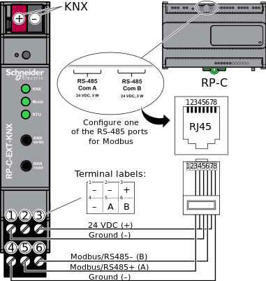
The KNX Modbus gateway (RP-C-EXT-KNX) is equipped with two 3-position pluggable screw terminal blocks for connection to the RP-C Modbus (RS-485) network and a 2-pole PCB connector for connection to the KNX bus.
You need to configure which RS-485 port (RJ45) on the RP-C controller to use for the Modbus network. You can configure to use either the RS-485 Com A port (default: Sensor bus) or RS-485 Com B port (default: Room bus). For more information, see Communication Ports on RP-C Models with “-F” in the Product Name .For more information, see Allocating Flexible Ports .
For the RP-C-12A-F-24V, RP-C-12B-F-24V, RP-C-12C-F-24V, and RP-C-16A-F-230V controller models, the rating for the RS-485 Com A port, the RJ45 pinout for the RS-485 Com B port, and the labeling of the two RS-485 ports differ between different hardware versions of the controllers. For more information, see Differences Between RP-C Hardware Versions .

The upper and lower screw terminal blocks are used as follows:
Upper: Power input from the RP-C through the controller's RS-485 port
Lower: Communication with the RP-C over the controller's Modbus network
The RS-485 Power Adapter (SXWNISORS485P10001) can be used to convert an RP-C controller's RS-485 port RJ45 interface to screw terminals. The adapter has a screw terminal for 24 VDC to support power supply from the controller to a device on the RS-485 based network. For more information, see Convert a BACnet/IP Controller RS-485 Interface .
|
Terminal number |
Designation |
Usage |
RP-C RS-485 Port RJ45 Pin |
|
Power input |
|
|
|
|
1 |
– |
Ground connection for supply voltage from the RP-C. |
5 a |
|
2 |
– |
Ground connection for supply voltage. Not connected to the RP-C. |
- |
|
3 |
+ |
Positive connection for supply voltage (24 VDC) from the RP-C. |
4, 7 |
|
Modbus |
|
|
|
|
4 |
– |
Ground connection for Modbus communication with the RP-C. |
8 a |
|
5 |
A |
Data line A (RS485+) for Modbus communication with the RP-C. |
3 |
|
6 |
B |
Data line B (RS485–) for Modbus communication with the RP-C. |
6 |
- RJ45 pins 5 and 8 are internally connected.
The KNX Modbus gateway uses a 4-conductor, 2-pole KNX connector for connection to the KNX bus.
|
Connector color |
Designation |
Usage |
|
Red |
+ |
Positive connection to KNX bus |
|
Dark gray |
– |
Ground connection to KNX bus |
 KNX Modbus Gateway RP-C-EXT-KNX
 Wiring
 Wire Sizes and Lengths for the KNX Modbus Gateway
 Communication Ports on RP-C Models with “-F” in the Product Name
 Allocating Flexible Ports
 Differences Between RP-C Hardware Versions
 RS-485 Power Adapter
 Convert a BACnet/IP Controller RS-485 Interface