Concept
Relay Outputs on CRS-HH-REL-10
The CRS-HH-REL-10 relay module has 10 relay outputs, which are designed for control of lights and blinds.
Do not connect high voltage (non-SELV/non-PELV) equipment and low voltage (SELV/PELV) equipment to relay outputs next to each other, as the clearance and creepage distance is not large enough for such connections. Connecting high (mains) voltage and low voltage equipment to relay outputs next to each other poses an electrical hazard that will result in death or serious injury.

There are six relay outputs on the upper side of the module, labeled DO1 to DO6, and four relay outputs on the lower side, labeled DO7 to DO10. To prevent from connecting high and low voltage next to each other, it is recommended not to mix high and low voltage connections on the same side of the device. Connect the high voltage equipment on the upper (DO1-DO6) or lower (DO7-DO10) side and connect low voltage equipment on the opposite side.

To control blinds, the relay module uses two consecutive relay outputs. When configuring a blind in EcoStruxure Building Operation WorkStation, two relay outputs (DO terminals) are allocated. You can only select an odd terminal number. This helps ensure that you do not connect a blind across sides, for example, from DO6 to DO7. For more information, see Relay 10 Module Overview .
Connection of a blind motor can only be made starting from an odd relay output terminal number.
The Hotel Application of the Connected Room Solutions for Hotels supports the use of a maximum of eight relay outputs (DOs) for blinds.
The relays can be inadvertently put in the On state due to mechanical shock during transportation. Ensure that the relay module is powered up by the RP-C room bus (24 VDC) before connecting the AC mains voltage to the loads (blind motors). Otherwise, there is a risk that the blinds or awnings are driven to their end position and cannot be retracted.
When a relay module is moved from one installation and reused in another installation, the module's “Cold start” and “System failure” values will be unknown. These values are stored in the module's persistent memory. The values control whether the relays will be on/active (energized) or off/inactive (de-energized) when the module is powered on (during a cold start) or powered off (due to a power outage). Connecting equipment to a relay module with unknown values on these properties entails a risk that the equipment will be damaged. To help prevent this risk, the module's relay outputs (DOs) need to be configured in EcoStruxure Building Operation WorkStation before connecting the equipment. The DOs are configured by binding the terminals to Blind or Relay objects. If a Relay object is used for the DO, the module's “Cold start value” and “System failure value” need to be configured to match the equipment to be connected. For more information, see Relay 10 Module Overview .
You can connect LED drivers in parallel to a relay output. Before doing so, ensure that the parallel connection of the LED drivers cannot cause the maximum inrush current of the relay output to be exceeded. If the maximum inrush current is exceeded, the relay can be damaged.
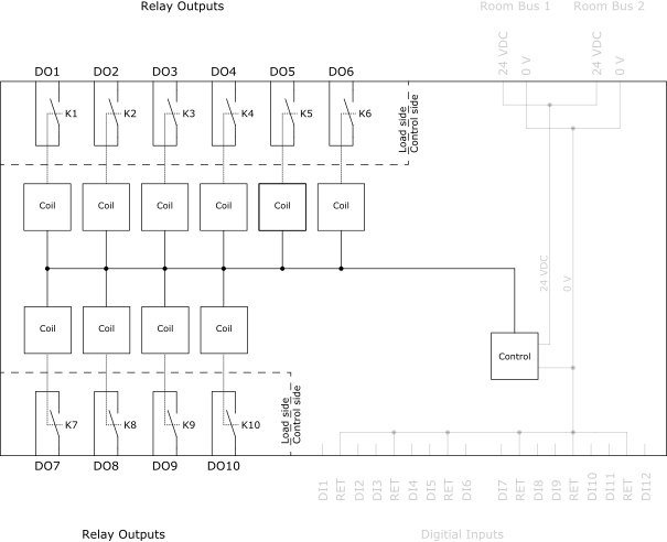
The 10 outputs are independent relay contacts. In the figure below, the relay contact is named K1 for the DO1 relay output, K2 for the DO2 relay output, and so on.

The module’s upper (DO1 to DO6) and lower (DO7 to DO10) load sides are galvanically separated from each other and from the control side. The control side is always SELV/PELV, and any or both load sides can be either mains voltage or SELV/PELV.
For Relay objects, you can configure the “Cold start value” and “System failure value”, which control whether the relays should be on/active (energized) or off/inactive (de-energized) under non-normal operating conditions such as when the module cold starts or loses communication with the RP-C controller. For more information, see Configuring Relays in RP Controller Expansion Relay 10 Modules . WorkStation does not have these configuration options for Blind objects. However, when a Blind object is bound to a terminal the module will internally configure these values appropriately.
In the event of a power outage, the relays are set to the “System failure value”. When the power supply returns, the relays are temporarily set to the “Cold start value” before the relay module has all its properties reinforced by the parent RP-C controller.
Specifications
Outputs
|
10, DO1 to DO10
|
Relay output rating
|
24 to 277 VAC, 50/60 Hz, 30 VDC:
|
Resistive and incandescent: 10 A
|
|
Standard magnetic ballast: 5 A
|
|
LED driver: 5 A
|
|
1/2 HP, 240 VAC, 50/60 Hz
|
|
1/4 HP, 120 VAC, 50/60 Hz
|
|
Maximum load current
|
Maximum 50 A total load for the 10 outputs
|
Maximum inrush current
|
Maximum 165 A inrush current (<20 ms) per output
|
Maximum 800 A inrush current (<200 µs) per output
|
 RP Controller Expansion Modules
 CRS-HH-REL-10
 Relay 10 Module Overview
 Relay 10 Module Blind Configuration
 Creating and Mapping Relay 10 Module Blinds
 Configuring Relays in RP Controller Expansion Relay 10 Modules
 Configuring Blinds in RP Controller Expansion Relay 10 Modules
 RP Controller Expansion Relay 10 Module Relay Properties - Basic Tab
 Danger