The RP controller expansion Insight-Sensor can be installed on a dropped (suspended) ceiling, a drywall ceiling, or a junction (gang) box.
Rules and Regulations
The Insight-Sensor must be professionally installed to comply with the following rules and regulations:
Part 15 of the Federal Communications Commission (FCC) rules
Innovation, Science and Economic Development Canada (ISED) licence-exempt Radio Standards Specifications (RSSs)
2014/53/EU Radio Equipment Directive (RED) of the European Union (EU).
S.I. 2017/1206 - Radio Equipment Regulations 2017 of the United Kingdom (UK)
Pour plus d'informations, voir RP Controller Expansion Insight-Sensor Regulatory Compliance and Approvals
.
General Installation Requirements
Horizontal installation in a ceiling
The Insight-Sensor is designed to be installed horizontally in a ceiling. The device can also be installed on a junction box when there is no ceiling and space is opened to plenum.
The Insight-Sensor must be installed with the passive infrared (PIR) sensor and thermal image sensor facing down. If the device is installed on a wall, the PIR sensor and thermal image sensor will not work properly.
|
Déclaration
|
|
REDUCED DEVICE PERFORMANCE
Failure to follow these instructions can result in reduced device performance.
|
action_zoom_plus_stroke

Figure :
Insight-Sensor installed horizontally, and without tilt, in a ceiling
Mounting height
With EcoStruxure Building Operation software version 6.0.1 and later, the Insight-Sensor supports mounting heights in the range from 2.3 to 3.3 m (7.5 to 10.8 ft). This is an extension of the range compared to previous software versions, which support mounting heights ranging from 2.5 to 3.0 m (8.2 to 10 ft). Installing the device higher than 3.3 m (10.8 ft) or lower than 2.3 m (7.5 ft) from the floor can significantly impair the performance of the people counting function. The height at which the device is installed must be configured in the EcoStruxure Building Operation software during commissioning. If the installed height is not correctly configured in the software, the counting accuracy may be degraded.
Pour plus d'informations, voir Configuring an Insight-Sensor
.
|
Déclaration
|
|
REDUCED DEVICE PERFORMANCE
Do not install the device higher than 3.3 m (10.8 ft) or lower than 2.3 m (7.5 ft) from the floor.
In the EcoStruxure Building Operation software, configure the height at which the device is installed.
Failure to follow these instructions can result in reduced device performance.
|
Déclaration
The mounting height of the Insight-Sensor is equal to the distance from the floor to the device, not the ceiling.
action_zoom_plus_stroke
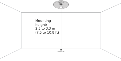
Figure :
Mounting height
Installation Orientation Restrictions
When two or more Insight-Sensor devices are installed next to or near each other (with overlapping detection areas), the devices must be oriented in the same direction, as shown in the figure below.
|
Déclaration
|
|
REDUCED THERMAL IMAGING SENSOR FUNCTION
When installing multiple devices in an open space, orient all devices in the same direction.
Failure to follow these instructions can result in reduced device performance.
|
|
Déclaration
|
|
REDUCED DEVICE PERFORMANCE
When replacing a device, install the new device in the same position and direction as the replaced device.
Failure to follow these instructions can result in reduced device performance.
|
Install all devices in line, oriented in the same direction, and with the thermal image sensors at a right angle to or parallel to the walls of the room, as shown in the figure below where the X and Y axes of thermal image sensors are indicated. Installing all devices according to these rules facilitates the configuration of people counting masks.
Pour plus d'informations, voir Insight-Sensor Masks
.
During installation, the Schneider Electric logo on the Insight-Sensor device must be on the right side when looking at the device installed in the ceiling.
Déclaration
When mounting rings are used, you can use the alignment notches on the rings to ensure that all devices are oriented in the same direction.
action_zoom_plus_stroke
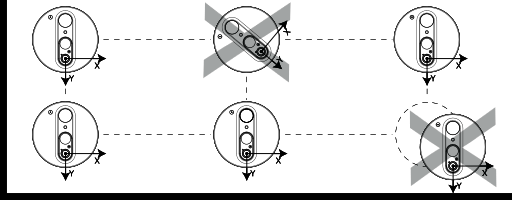
Figure :
Installation orientation restrictions
Use of Masks to Adjust the Detection Area
When installing Insight-Sensor devices in an open space or large meeting room, it is important to consider and manage the following:
Overlapping detection areas between Insight-Sensor devices
Presence of windows, radiators, or other objects in the same temperature range as a human body
If two or more Insight-Sensor devices are installed too close, the persons present in the thermal image sensors' overlapping detection areas may be counted twice.
If an Insight-Sensor is installed so that the thermal image sensor's detection area includes a window heated by solar rays, a radiator, or other large object in the same temperature range as a human body, people close to the hot object may not be detected, or the hot object may be counted as a person.
|
Déclaration
|
|
REDUCED DEVICE PERFORMANCE
Do not install the device close to an exterior window.
Failure to follow these instructions can result in reduced device performance.
|
As it can be difficult to move Insight-Sensor devices, which is partly because the devices are wired and partly because the PIR sensor means restrictions on the installation of the devices, the solution may instead be to adjust the thermal image sensor's detection areas for the devices during installation.
Using the EcoStruxure Building Operation software, the thermal image sensor's detection area can be configured to reduce overlapping areas between two devices to minimize the risk of a person being counted twice. The detection area can also be adjusted to exclude heat radiating objects such as radiators and windows heated by solar rays, and to exclude corridors and other adjacent areas through which people just pass by.
Pour plus d'informations, voir Insight-Sensor Masks
.
Installation Using the Mounting Springs
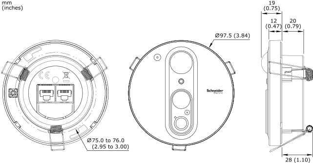
The Insight-Sensor is typically installed on a dropped ceiling. For that reason, the Insight-Sensor is delivered with three flexible mounting brackets (springs) preinstalled on the device. The mounting springs enable quick and easy installation of the device on a dropped ceiling. The installation requires a clearance hole with a diameter of 75 to 76 mm (2.95 to 3.00 inches) in the ceiling tile.
action_zoom_plus_stroke

Figure :
Insight-Sensor installed on a dropped ceiling
The Multi-sensor (RP-C-EXT-MS-BLE) and Insight-Sensor (RP-C-EXT-IS-BLE) are the same size and have the same cabling. This means an already installed Multi-sensor can easily be replaced with an Insight-Sensor, or vice versa.
Installation Using the Mounting Ring
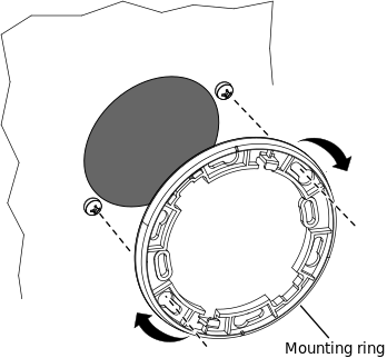
The Insight-Sensor also comes with a mounting ring, which enables the following alternative installation methods:
Déclaration
The RP-C-EXT-MR-K5 SpaceLogic Sensor Mounting Ring Kit is available when there is a need to order additional, spare mounting rings. The kit contains five mounting rings. The kit has the part number SXWREMR5XX10001.
Installation on a junction box
The Insight-Sensor can be installed on a junction box when there is no ceiling and space is opened to plenum. The installation requires an octagon junction box of size 4.0 inches (102 mm) and a minimum depth of 1.0 inches (25.5 mm).
Déclaration
The octagon junction box is not included.
action_zoom_plus_stroke
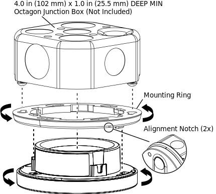
Figure :
Insight-Sensor installed on an octagon junction box
Déclaration
You can use the two alignment notches on the mounting ring to position the device.
Installation on a drywall ceiling
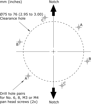
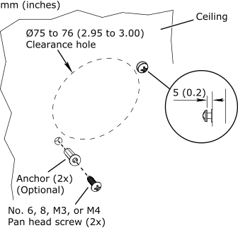
The mounting ring also makes it possible to install the Insight-Sensor on a drywall ceiling using an appropriate anchoring system. The installation requires a clearance hole with a diameter of 75 to 76 mm (2.95 to 3.00 inches) and two mounting holes that fit number 6, 8, M3, or M4 screws (with or without anchors) in the drywall ceiling. You can use the 1:1 drill template in the installation sheet, which comes with each Insight-Sensor, to measure out the location of the holes. You can also use the mounting ring to measure out the holes.
action_zoom_plus_stroke
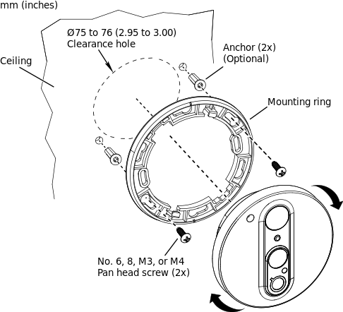
Figure :
Insight-Sensor installed on a drywall ceiling

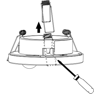
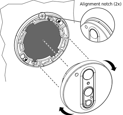
 RP Controller Expansion Insight-Sensor Device Installation
 Connecting RP Controller Expansion Modules to an RP Controller
 Configuring the Room Bus Address for an RP Controller Expansion Sensor Module
 Installing an RP Controller Expansion Insight-Sensor into a Dropped Ceiling Using the Mounting Springs
 Installing an RP Controller Expansion Insight-Sensor on an Octagon Junction Box Using the Mounting Ring


