Concept
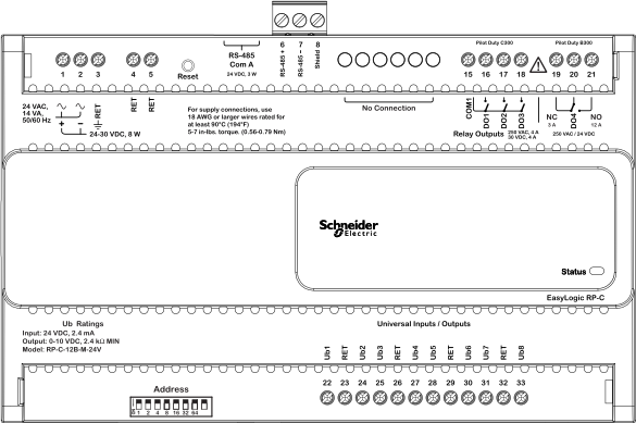
RP-C-12B-M-24V Screw Terminals
The RP-C-12B-M-24V model has 12 I/O points and the controller is equipped with 24 fixed screw terminals and a 3-position removable screw terminal block.
Recommended screw tightening torque: 0.56 to 0.79 Nm (5 to 7 lbf.in)

The 24 fixed screw terminals are used as follows:
Two screw terminals for the power input
One screw terminal for ground input
Two screw terminals for the return (RET) terminals 4 and 5
Four screw terminals for the three relay outputs
Three screw terminals for the high power relay output
12 screw terminals for the eight universal inputs/outputs of type Ub
The 3-position removable screw terminal block is used for connection to the BACnet MS/TP (RS-485) network.
|
Terminal number |
Designation |
Usage |
|
Power input |
|
|
|
1 |

|
24 VAC, 50/60 Hz, 14 VA Positive lead (+) when operating the device from 24-30 VDC, 8 W |
|
2 |

|
The other output from the 24 VAC transformer connects to terminal 2. Negative (–) lead when operating the device from 24-30 VDC, 8 W |
|
3 |
RET 
|
Terminal 3 is provided for convenience to connect to protective earth ground. |
|
Return terminals |
|
|
|
4 |
RET |
Internally connected to all earth ground and RET terminals |
|
5 |
RET |
Internally connected to all earth ground and RET terminals |
|
RS-485 terminals |
|
|
|
6 |
RS-485+ |
Connection to TX/RX+ (RS-485+) signal in the BACnet MS/TP (RS-485) network. |
|
7 |
RS-485– |
Connection to TX/RX– (RS-485–) signal in the BACnet MS/TP (RS-485) network. |
|
8 |
Shield |
Convenience terminal to interconnect two shield drain wires (incoming and outgoing). There is no electrical connection in the device. The shield should be connected to ground at only one location and that is recommended to be at the automation server. The shield should not be connected directly to the RET terminal on the automation server. The transient energy on the drain wire should be conducted to ground and not through the automation server. |
|
Relay outputs |
|
|
|
15 |
COM1 |
Common connection for DO1, DO2, and DO3 |
|
16 |
DO1 |
Relay output, type Form A |
|
17 |
DO2 |
Relay output, type Form A |
|
18 |
DO3 |
Relay output, type Form A |
|
High power relay outputs |
|
|
|
19 |
NC |
Normally Closed terminal. High power relay output, type Form C. |
|
20 |
DO4 |
Common terminal. High power relay output, type Form C. |
|
21 |
NO |
Normally Open terminal. High power relay output, type Form C. |
|
Universal inputs/outputs |
|
|
|
22 |
Ub1 |
Universal input/output, type Ub |
|
23 |
RET |
Internally connected to all earth ground and RET terminals |
|
24 |
Ub2 |
Universal input/output, type Ub |
|
25 |
Ub3 |
Universal input/output, type Ub |
|
26 |
RET |
Internally connected to all earth ground and RET terminals |
|
27 |
Ub4 |
Universal input/output, type Ub |
|
28 |
Ub5 |
Universal input/output, type Ub |
|
29 |
RET |
Internally connected to all earth ground and RET terminals |
|
30 |
Ub6 |
Universal input/output, type Ub |
|
31 |
Ub7 |
Universal input/output, type Ub |
|
32 |
RET |
Internally connected to all earth ground and RET terminals |
|
33 |
Ub8 |
Universal input/output, type Ub |
 RP-C Controllers
 RP-C Screw Terminals
 Wiring
 Danger