
Hardware Installation
SpaceLogic™ CRS-HH-REL-10
Safety Information
Electrical equipment should be installed, operated, serviced, and maintained only by qualified personnel. No responsibility is assumed by Schneider Electric for any consequences arising out of the use of this material.
Carefully read these instructions and all information relevant for this product before trying to install it. See the list of technical literature.
Technical Literature
SpaceLogic and EasyLogic - Hardware Installation System Guide, 04-XX001-XX-en
The technical literature and declarations of conformity can be accessed on the Schneider Electric extranet, ecoxpert.se.com. Contact your local Schneider Electric sales office for a hard copy of the documentation or for additional information.


Connections
 Danger
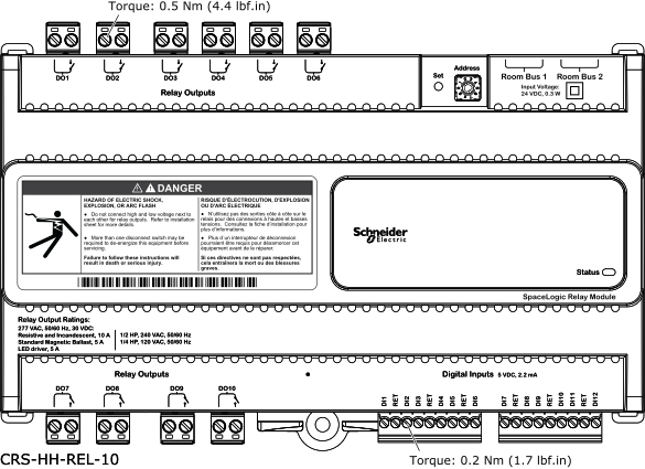
To prevent from connecting high and low voltage next to each other, it is recommended not to mix high and low voltage connections on the same side of the device. Connect the high voltage equipment on the upper (DO1-DO6) or lower (DO7-DO10) side and connect low voltage equipment on the opposite side.

Wiring
Recommended screw tightening torques:
2-pole connector: 0.5 Nm (4.4 lbf.in)
9-pole connector: 0.2 Nm (1.7 lbf.in)
For information on wiring, see the SpaceLogic and EasyLogic - Hardware Installation System Guide.
Part Numbers
|
Product |
Part number |
|
CRS-HH-REL-10 Includes pluggable screw terminal blocks (10 x 2-pole, 2 x 9-pole connectors) for the I/O, delivered in a plastic bag with the device. |
SXWHHREL10001
|
|
DIN-rail end clip, 25 pieces |
SXWDINEND10001 |
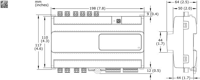
Specifications
| DC input | |
DC input supply voltage
|
24 VDC
|
Powered by the RP-C through the room bus (RJ45)
|
|
Maximum power consumption
|
0.3 W
|
| Port types | |
Room bus
|
RS-485
|
Dual RJ45 ports for daisy-chain configurations
|
|
| Operation environment | |
Ambient temperature, operating
|
0 to 50 °C (32 to 122 °F)
|
Humidity
|
20 to 90 % RH non-condensing
|
Pollution degree
|
2
|
| Mechanical | |
Ingress protection rating
|
IP 20
|
Plastic flame rating
|
UL94 V-0
|
Plenum rating
|
UL 2043 (Approved for plenum installations)
|
| Relay outputs | |
Outputs
|
10, DO1 to DO10
|
Relay output rating
|
24 to 277 VAC


|
Resistive and incandescent: 10 A
|
|
Standard magnetic ballast: 5 A
|
|
LED driver: 5 A
|
|
1/2 HP, 240 VAC, 50/60 Hz
|
|
1/4 HP, 120 VAC, 50/60 Hz
|
|
Maximum load current
|
Maximum 50 A total load for the 10 outputs
|
Maximum inrush current
|
Maximum 165 A inrush current (<20 ms) per output
|
Maximum 800 A inrush current (<200 µs) per output
|
|
| Digital inputs | |
Inputs
|
12, DI1 to DI12
|
Input rating
|
5 VDC
|
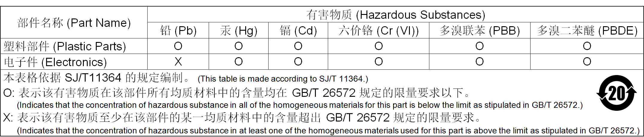
Addendum - California Proposition 65 Warning Statement for California Residents

 RP Controller Expansion Module Device Installation
I/O Wiring
Communication Port Wiring
CRS-HH-REL-10
Hardware Overview
RP Controller Expansion Module Device Installation
I/O Wiring
Communication Port Wiring
CRS-HH-REL-10
Hardware Overview