
Hardware Installation
SpaceLogic™ RP-C-EXT-0-10V-4-PD and RP-C-EXT-0-10V-4
Safety Information
Electrical equipment should be installed, operated, serviced, and maintained only by qualified personnel. No responsibility is assumed by Schneider Electric for any consequences arising out of the use of this material.
Carefully read these instructions and all information relevant for this product before trying to install it. See the list of technical literature.
Technical Literature
SpaceLogic and EasyLogic - Hardware Installation System Guide, 04-XX001-XX-en
The technical literature and declarations of conformity can be accessed on the Schneider Electric extranet, ecoxpert.se.com. Contact your local Schneider Electric sales office for a hard copy of the documentation or for additional information.


 Danger

Wiring
For information on wiring, see the SpaceLogic and EasyLogic - Hardware Installation System Guide.
Part Numbers
|
Product |
Part number |
|
RP-C-EXT-0-10V-4-PD
|
SXWRE0104PD10001
|
|
RP-C-EXT-0-10V-4
|
SXWRE010410001
|
|
DIN-rail end clip, 25 pieces |
SXWDINEND10001 |
|
Mounting plate - RP controller expansion modules, 5 pieces |
SXWREMPK510001
|
Required External Connectors
|
Use |
Part number |
Reference |
Connector type |
Suitable for cable diameters mm (inches) |
Tightening torque, screws Nm (lbf.in) |
Marking |
Color of coding /housing |
Minimum order quantity |
|
Power supply input |
SXWRPCCONWWPOW |
91.931.4053.1 |
Female |
5.6–11 (0.22–0.43) |
0.3–0.5 (2.7–4.4) |
L, PE, N |
Black /Black |
100 |
|
Light outputs (RP-C-EXT-0-10V-4-PD) |
SXWRPCCONWWLIGHTPD |
91.952.4453.0 |
Male |
8.5–12.5 (0.34–0.49) |
0.3–0.5 (2.7–4.4) |
N, PE, L, D2, D1 D2: AO1..4 D1: COM |
Pastel blue /White |
50 |
|
Light outputs (RP-C-EXT-0-10V-4) |
SXWRPCCONWWLIGHT2 |
91.922.3353.0 |
Male |
6–7.7 (0.24–0.30) |
0.3–0.5 (2.7–4.4) |
2, 1 2: AO1..4 1: COM |
Light blue /White |
100 |
|
Digital inputs |
SXWRPCCONWDI |
91.921.2353.0 |
Female |
3.4–5.5 (0.14–0.21) |
0.3–0.5 (2.7–4.4) |
1, 2 1: DI1..4 2: RET |
Light blue /White |
100 |
The external connectors need to be ordered separately. The connectors can be ordered in quantities of 50 or 100 from Schneider Electric using the above part numbers. The connectors can also be ordered directly from Wieland using the above reference numbers. For more information, see the Wieland Electric web site.
Specifications
| AC input, RP-C-EXT-0-10V-4-PD | |
Nominal voltage
|
230 VAC

|
Maximum current consumption
|
10 A
|
Overvoltage category
|
III
|
| AC input, RP-C-EXT-0-10V-4 | |
Nominal voltage
|
100 to 277 VAC
|
Power consumption
|
10 VA
|
Overvoltage category
|
III
|
| DC input | |
Room bus power consumption
|
0.3 W (24 VDC)
|
| Port types | |
Room bus
|
RS-485
|
Dual RJ45 ports for daisy-chain configurations
|
|
| Operation environment | |
Ambient temperature, operating
|
0 to 50 °C (32 to 122 °F)
|
Humidity
|
20 to 90 % RH non-condensing
|
Pollution degree
|
2
|
| Mechanical, RP-C-EXT-0-10V-4-PD | |
Ingress protection rating
|
IP 20
|
Plastic flame rating
|
UL94 V-0
|
| Mechanical, RP-C-EXT-0-10V-4 | |
Ingress protection rating
|
IP 20
|
Plastic flame rating
|
UL94 V-0
|
Plenum rating
|
UL 2043 (Approved for plenum installations)
|
| 0-10V light outputs, RP-C-EXT-0-10V-4-PD | |
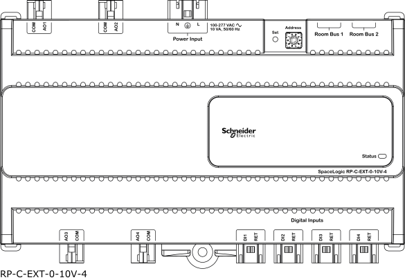
Outputs
|
4, Light 1 to Light 4
|
AO1..4 : Analog output terminal
|
|
COM : Common terminal
|
|
Maximum source/sink current
|
10 mA per output
|
Power distribution
|
230 VAC (same voltage as power supply)
|
Maximum 5 A load per output
|
|
Maximum 10 A total load for the 4 outputs
|
|
Maximum 165 A inrush current (<20 ms) per output
|
|
Maximum 800 A inrush current (<200 µs) per output
|
|
| 0-10V light outputs, RP-C-EXT-0-10V-4 | |
Outputs
|
4, Light 1 to Light 4
|
AO1..4 : Analog output terminal
|
|
COM : Common terminal
|
|
Maximum source/sink current
|
10 mA per output
|
| DI – Digital inputs | |
Input rating
|
5 VDC

|
Inputs
|
4
|
 RP Controller Expansion Module Device Installation
I/O Wiring
Communication Port Wiring
RP-C-EXT-0-10V-4-PD
RP-C-EXT-0-10V-4
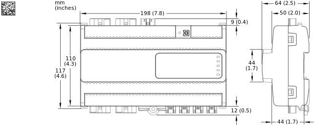
Hardware Overview
RP Controller Expansion Module Device Installation
I/O Wiring
Communication Port Wiring
RP-C-EXT-0-10V-4-PD
RP-C-EXT-0-10V-4
Hardware Overview