
Hardware Installation
EasyLogic™ RP-V-5C-M
Part number: SXWRPV5CM10001
Safety Information
Electrical equipment should be installed, operated, serviced, and maintained only by qualified personnel. No responsibility is assumed by Schneider Electric for any consequences arising out of the use of this material.
Carefully read these instructions and all information relevant for this product before trying to install it. See the list of technical literature.
Technical Literature
SpaceLogic and EasyLogic - Hardware Installation System Guide, 04-XX001-XX-en
The technical literature and declarations of conformity can be accessed on the Schneider Electric extranet, ecoxpert.se.com. Contact your local Schneider Electric sales office for a hard copy of the documentation or for additional information.

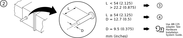
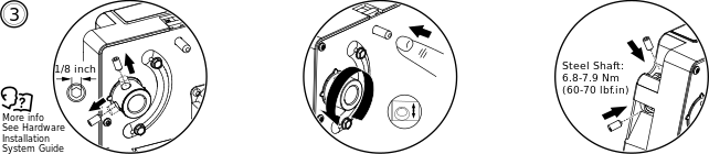
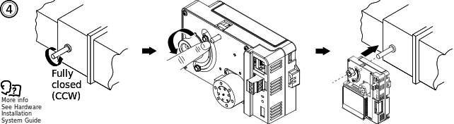
Moving the Damper Shaft Mounting Screws to the Alternative Positions for Short Shafts Only
Wiring
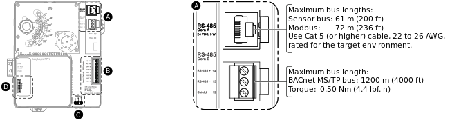
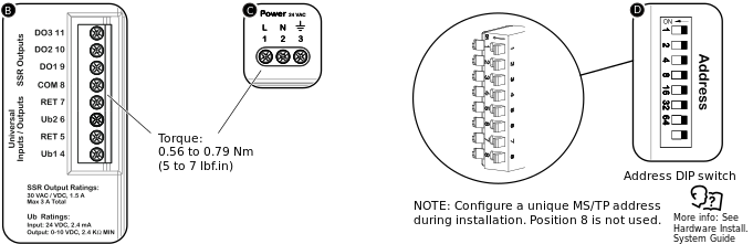
Recommended screw tightening torque for removable screw terminal block : 0.5 Nm (4.5 lbf.in)
Recommended screw tightening torque for fixed screw terminal blocks: 0.56 to 0.79 Nm (5 to 7 lbf.in)
For information on wiring, see the SpaceLogic and EasyLogic - Hardware Installation System Guide.
Configuring a Unique MS/TP Address
Configure a unique MS/TP address for the device during installation. Use position 1 to 7 on the Address DIP switch. Position 1 to 7 represent the binary values 1, 2, 4, 8, 16, 32, and 64. For example, to configure MS/TP address 6, set DIP switches 2 and 3 to ON and switches 1, 4, 5, 6, and 7 to OFF. For more information, see the SpaceLogic and EasyLogic - Hardware Installation System Guide.
Part Numbers
|
Product |
Part number |
|
RP-V-5C-M
|
SXWRPV5CM10001
|
|
Adapter for damper shaft diameter 9.5 mm (3/8 inch) |
AM-135 |
Specifications
| AC input | |
Nominal voltage
|
24 VAC

|
Power consumption
|
11 VA
|
| Port types | |
RS-485 port Com A
|
24 VDC, 3 W, RS-485 (RJ45)
|
RS-485 port Com B
|
RS-485 (3-pole screw terminal block)
|
| Operation environment | |
Ambient temperature, operating
|
0 to 50 °C (32 to 122 °F)
|
Humidity
|
Maximum 95 % RH non-condensing
|
| Mechanical | |
Ingress protection rating
|
IP 20
|
Plastic flame rating
|
UL94 V-0
|
Plenum rating
|
UL 2043 (Approved for plenum installations)
|
| Ub – Universal I/O | |
Input rating
|
24 VDC

|
Voltage output rating
|
0 to 10 VDC
|
Channels
|
2
|
| DO – Solid-state relay outputs | |
Output rating
|
30 VAC
|
Max. 3 A total load
|
|
Channels
|
3
|
Addendum - California Proposition 65 Warning Statement for California Residents

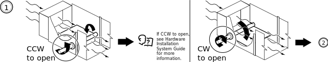
 RP-V Device Installation
I/O Wiring
Communication Port Wiring
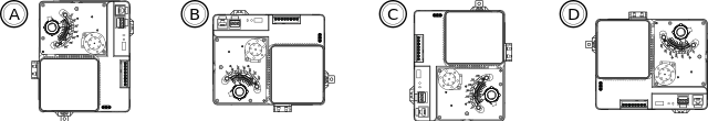
RP-V Controllers
Hardware Overview
RP-V Device Installation
I/O Wiring
Communication Port Wiring
RP-V Controllers
Hardware Overview