
Hardware Installation
SpaceLogic™ TB-IO-W1
Part number: SXWTBIOW110001
Safety Information
Electrical equipment should be installed, operated, serviced, and maintained only by qualified personnel. No responsibility is assumed by Schneider Electric for any consequences arising out of the use of this material.
Carefully read these instructions and all information relevant for this product before trying to install it. See the list of technical literature.
Technical Literature
SpaceLogic and EasyLogic - Hardware Installation System Guide, 04-XX001-XX-en
EcoStruxure Building Management - Smoke Control System Design Guide, 04-16014-XX-en
The technical literature and declarations of conformity can be accessed on the Schneider Electric extranet, ecoxpert.se.com. Contact your local Schneider Electric sales office for a hard copy of the documentation or for additional information.
 Warning
Terminal Base and Applicable Electronics Modules (-H indicates Override Switch)
|
Device |
Part number |
|
TB-IO-W1 Terminal Base |
SXWTBIOW110001 |
|
DI-16 |
SXWDI16XX10001 |
|
UI-16 |
SXWUI16XX10001 |
|
RTD-DI-16 |
SXWRTD16X10001 |
|
DO-FA-12 |
SXWDOA12X10001 |
|
DO-FA-12-H |
SXWDOA12H10001 |
|
DO-FC-8 |
SXWDOC8XX10001 |
|
DO-FC-8-H |
SXWDOC8HX10001 |
|
AO-8 |
SXWAO8XXX10001 |
|
AO-8-H |
SXWAO8HXX10001 |
|
AO-V-8 |
SXWAOV8XX10001 |
|
AO-V-8-H |
SXWAOV8HX10001 |
|
UI-8/DO-FC-4 |
SXWUI8D4X10001 |
|
UI-8/DO-FC-4-H |
SXWUI8D4H10001 |
|
UI-8/AO-4 |
SXWUI8A4X10001
|
|
UI-8/AO-4-H |
SXWUI8A4H10001 |
|
UI-8/AO-V-4 |
SXWUI8V4X10001 |
|
UI-8/AO-V-4-H
|
SXWUI8V4H10001 |
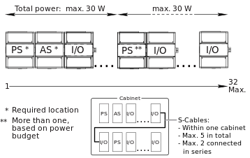
S-Cables
|
Device |
Part number |
|
S-Cable, 1.5 m, angle |
SXWSCABLE10002 |
|
S-Cable, 0.75 m, angle |
SXWSCABLE10003 |
Smoke Control Application Note
All Universal Inputs (UI), Digital Inputs (DI), and Analog Outputs (AO) are power-limited per UL 864 requirements. All Digital Output (DO) relays are non-power-limited. For more information on the use of the I/O modules for a UL 864 smoke control application, see the latest version of the EcoStruxure Building Management - Smoke Control System Design Guide (04-16014-XX-en).
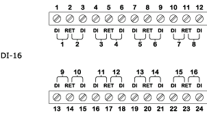
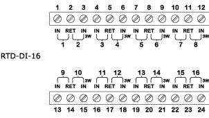
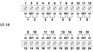
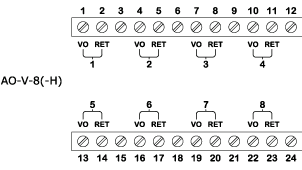
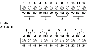
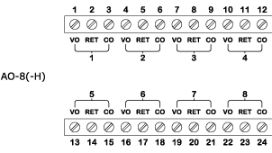
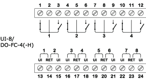
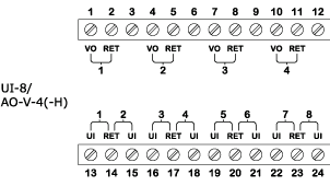
Connections for I/O Modules


Specifications
| Operation environment | |
Ambient temperature, operating
|
0 to 50 °C (32 to 122 °F)
|
Humidity
|
Maximum 95 % RH non-condensing
|
| Mechanical | |
Ingress protection rating
|
IP 20
|
Plastic flame rating
|
UL94-5VB
|
| Electrical | |
I/O bus power
|
24 VDC

|
Maximum addresses per I/O bus
|
32
|
| DI-16 Module | |
DC input power
|
24 VDC
|
Input rating
|
24 V, 2.4 mA
|
Channels
|
16 input
|
| UI-16 Module | |
DC input power
|
24 VDC
|
Input rating
|
24 V, 2.4 mA
|
Channels
|
16 input
|
| RTD-DI-16 Module | |
DC input power
|
24 VDC
|
Input rating
|
24 V, 2.4 mA
|
Channels
|
16 input
|
| DO-FA-12(-H) Module | |
DC input power
|
24 VDC
|
Relay contact rating
|
250 VAC

|
Pilot Duty (Power Factor 0.35)
|
|
Channels
|
12 output
|
| DO-FC-8(-H) Module | |
DC input power
|
24 VDC
|
Relay contact rating
|
250 VAC
|
Pilot Duty (Power Factor 0.35)
|
|
Channels
|
8 output
|
| AO-8(-H) Module | |
DC input power
|
24 VDC
|
Voltage output rating
|
0 to 10 VDC
|
Current output rating
|
0 to 20 mA, 650 ohm (max.)
|
Channels
|
8 output
|
| AO-V-8(-H) Module | |
DC input power
|
24 VDC
|
Voltage output rating
|
0 to 10 VDC
|
Channels
|
8 output
|
| UI-8/DO-FC-4(-H) Module | |
DC input power
|
24 VDC
|
Relay contact rating
|
250 VAC
|
Pilot Duty (Power Factor 0.35)
|
|
Input rating
|
24 V, 2.4 mA
|
Channels
|
4 output/8 input
|
| UI-8/AO-4(-H) Module | |
DC input power
|
24 VDC
|
Voltage output rating
|
0 to 10 VDC
|
Current output rating
|
0 to 20 mA, 650 ohm (max.)
|
Input rating
|
24 V, 2.4 mA
|
Channels
|
4 output/8 input
|
| UI-8/AO-V-4(-H) Module | |
DC input power
|
24 VDC
|
Voltage output rating
|
0 to 10 VDC
|
Input rating
|
24 V, 2.4 mA
|
Channels
|
4 output/8 input
|
Addendum - California Proposition 65 Warning Statement for California Residents

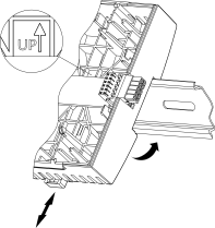
 Device Installation
I/O Wiring
Terminal Bases
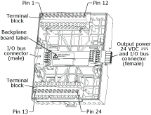
Hardware Overview
Device Installation
I/O Wiring
Terminal Bases
Hardware Overview