Concetto
Network Accessories
Network accessories include the following:
bLINK Series MS/TP Repeaters
EIS Series Ethernet switches
MS/TP Network Bias Supply
Transformers
DC Power Supply
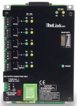
You use the bLINK Series MS/TP Repeaters (the bLINK-AC-S, the bLINK-DC-S, the bLINK-F-AC-S, and the bLINK-F-DC-S) to provide an RS-485 repeating function between multiple BACnet MS/TP ports. The -F models also provide two fiber optic ports for extending the MS/TP network over fiber and dropping the copper MS/TP interface at a remote location with EMI immunity over the fiber extension. A 24 VDC power supply powers the -DC models and the -AC models are powered by 120 VAC line voltage.

All four models pass the standard BACnet MS/TP protocol through the five, provided RS-485 ports. You can use these units to extend the MS/TP bus length or segment excess node counts. The repeaters may have UUKL listed product on any or all ports. They have also been approved by UL 864 for use as an isolation device where non-UUKL product may be isolated on one or more of the ports. UUKL listed controllers used in the smoke control application must not be placed on the MS/TP bus segments containing any non-UUKL devices.
For UL 864 compliance, any non-UUKL product must have a UL listing (of some type in order to reduce the risk of shock and fire) before it can be connected to an open/available repeater port (that is not used for connecting to any smoke control controllers).
The Ethernet IP communications between all IP level controllers and devices participating in the smoke control applications must be transported though UL864 recognized (UL 508 Listed) Ethernet Interconnect Switches to connect the smoke control system components.

Four models of the EIS series Ethernet switches from Contemporary Controls are approved for this function:
EIS8-100T
EIS6-100T/FT
EIS6-100T/FC
EIS6-100T/FCS
The models are UL 508 Listed and UL 864 recognized UOXX2 under UL file S8112. The model EIS8-100T is used for copper (wire) connections and provides eight RJ-45 ports for connection of standard CAT-5 LAN cables switching 10/100Mbps Ethernet data between the eight ports.
For longer distances or to extend Ethernet through high EMI environments, the EIS6-100T/FT, EIS6-100T/FC or EIS6-100T/FCS models can be applied. These three models each provide four RJ-45 10/100MBps ports for connecting standard CAT-5 LAN cables and also provide two fiber optic network ports for long distance, high speed Ethernet network expansion. On the EIS6-100T/FT, each fiber optic port consists of two ST type fiber connectors, one for transmit and one for receive.
On the EIS6-100T/FC, each fiber optic port consists of two SC type fiber connectors, one for transmit and one for receive. Both the EIS6-100T/FT and EIS6-100T/FC models provide fiber connections using 50/125 or 62.5 um multimode fibers that offer the capability for driving distances up to 2 km between the fiber switch units. When single mode fiber is encountered on a project, the model EIS6-100T/FCS can be applied. It has the same appearance and SC fiber ports as the model EIS6-100T/FC, except the internal fiber interface supports 1300 nm single mode fiber up to a length of 15 km.
The long distance is not considered applicable to the typical smoke control system. However, single mode fiber may be encountered and this model is required to interface with such fiber. On all three fiber optic models, the dual fiber ports provide a simple means to distribute a fiber bus through a facility with the incoming fiber pair simply connecting to one fiber port and the outgoing fiber pair connecting to the second fiber port creating a fiber optic daisy chain bus. This permits a simple, reliable and high-speed fiber network to run through areas associated with smoke control applications over potentially significant distances.
When the EIS Ethernet Switch is used to transport smoke control application commands, the Smoke Control Servers must supervise communications integrity through the EIS to the smoke control application interfaces and controllers on the other side. The FSCS controller is configured to enunciate any communications faults detected when connecting with the smoke control application controllers. The EIS is housed within a metal enclosure (7.5 inch High (190.5 mm) x 1.75 inch Wide (44.44 mm) x 5.5 inch Deep (149.7 mm)) and provides keyholes on a rear bracket for panel mounting.
You must install the EIS within one of the approved enclosures. Per maggior informazioni, consulta Smoke Control Enclosures and Requirements .
The EIS is powered by 24 VAC (10 VA) using any of the approved transformers. Per maggior informazioni, consulta Transformers .
The I/A Series MNB MS/TP controllers require a 5 volt bias on the MS/TP network bus. (This is true only for the Automation Server (AS-SMK) and not the AS-P (AS-P-SMK)).
When a MNB-300 controller is used and positioned at the ends of the bus, it provides network bias via its plug-on bias resistor connections.
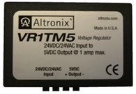
When an MNB-300 is not positioned at the end of the network bus, and the cable length exceeds 500 feet, you can use an external isolated 5 volt supply to bias the network. The supply you use for this purpose is the Altronix model VR1TM5 bias supply. This model is configured on the bus as described in the installation section of the guide. Per maggior informazioni, consulta MS/TP Cable Routing .

The majority of the UUKL listed products discussed in this guide are powered by 24 VAC. This table lists the approved transformer models for all of the products designated to receive 24 VAC.
|
Transformer |
Description |
|
EMSC-541 |
50VA , 120V Primary, 24V Secondary, 50/60 Hz, Non-replaceable Fuse in Primary |
|
EMSC-542 |
100VA , 120V Primary, 24V Secondary, 50/60 Hz, Non-replaceable Fuse in Primary |
|
EMSC-543 |
240VA , 120V Primary, 24V Secondary, 60 Hz, Non-replaceable Fuse in Primary |
|
EMSC-583 |
75VA , 120V Primary, 24V Secondary., 50/60 Hz, Class 2 |
|
EMSC-616 |
75VA , 120V Primary 24 V Secondary, 50/60 Hz, Class 2, Foot Mount single Hub UL-Listed with Circuit Breaker, Mounting Plate included |
|
EMSC-618 |
96VA , 120V Primary, 24V Secondary, 50/60 Hz, Class 2, Foot Mount single Hub UL-Listed with Circuit Breaker, Mounting Plate included |
|
024-024-040-TF |
40VA , 24V Primary, 24V Secondary, 50/60 Hz, 24V to 24V Isolation Transformer |
|
01-2100-323 |
40 VA , 120 VAC Primary, 24 V Secondary, 60 Hz |
Per maggior informazioni, consulta Transformers .
For products requiring 24 VDC power, the PS120/240-AC65U-S and PS120/240-AC65-S model power supply modules are available. These supply modules deliver an output of 24 VDC and are rated for loads up to 50W. The supply module is DIN rail mounted with AC input power connected via a terminal block positioned in the lower left corner (under the removable cover). The unit is switch-selectable for 120 VAC to 240 VAC input and the 24 VDC output is supplied with a 5 position connector positioned on the right side of the unit. The 24 VDC is delivered on terminal 5 and the supply output common is on terminal 4.
 SmartStruxure Solution Hardware Overview
 StruxureWare Building Operation Overview
 MS/TP BACnet Controllers
 Smoke Control Enclosures and Requirements
 MS/TP Cable Routing
 Transformers