Pojęcie
FSCS Communication Status
The Smoke Control Server managing the FSCS must monitor the integrity of the communications link to all other controllers that have any participation in the smoke control application. This will as a minimum include all controllers that manage air handling equipment presented on the FSCS graphic.
In the case of unitary equipment controllers such as VAV, it is recommended that a Smoke Control Server in the area be assigned as the zone manager and have that controller perform the communications supervision to the subordinate unitary controllers and programmable controllers. Communications to the zone manager will be supervised from the FSCS manager (Smoke Control Server) and the zone manager will report any subordinate controller communications faults to the FSCS manager just as it does with equipment status and equipment fault updates. Depending on the level of detail desired for the presentation on the FSCS, the zone manager may be configured to summarize all of its subordinate controller communications into a single status bit, or you may have a unique bit for each controller. The recommended technique for supervising the communications from the FSCS manager is presented in the example smoke control system described in the following text.
Supervision of the communications with the MS/TP field controllers is performed from the Smoke Control Server serving the MS/TP bus. The following technique is suggested:
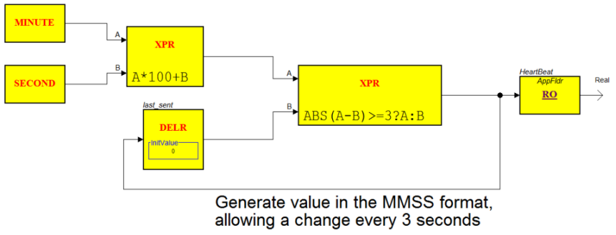
1) Within each of the MS/TP controllers, provide a Script application that generates a new output value every 3 seconds. The value should be continuously changing and it is suggested that you form the value with the sum of current minutes plus seconds (minutes X 100 + seconds) forming a 4 digit value of MMSS. The minute/second content of the value can be useful when it is necessary to perform any serial data captures and analysis.
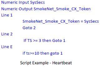
The following example Script program in b3 controllers generates the 3 second Heartbeat value.

2) In the Smoke Control Server, BACnet COV subscriptions are set up to receive the heartbeat values upon any change.
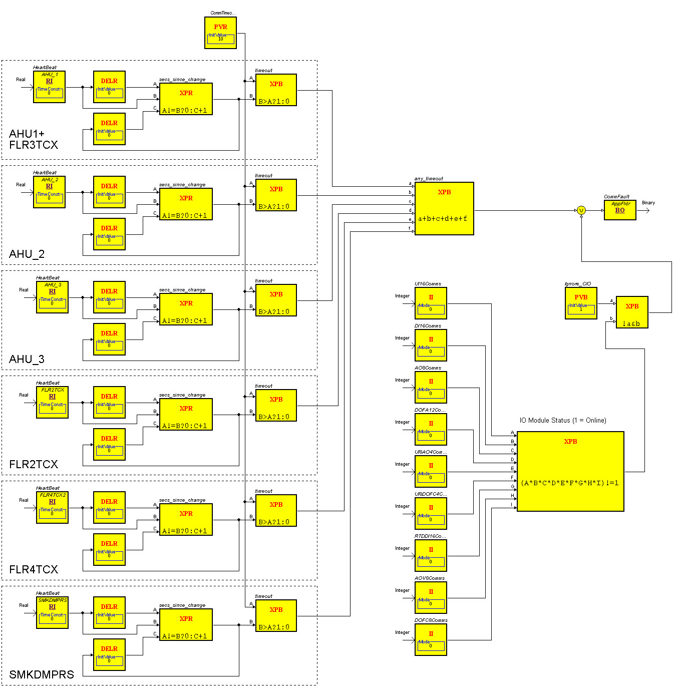
3) The following is an example Function Block program in the Smoke Control Server that monitors the heartbeat values coming from each of the MS/TP controllers. Only the AHU_1 and AHU_2 heartbeat inputs are seen. The others come in on the inputs C to I of the XPB.
In the dashed line box, the heartbeat is received and the current value is compared with the previous value. If the incoming value changes, the seconds timer generated by the XPR block is reset to zero. When the value is not changing, the XPR block’s output will increment (counting up) with each second. The XPR block output (seconds since last heartbeat) goes into the XPB block which compares the counter with the maximum delay set by the PVR block. The maximum is 10 seconds in the example. A value greater than 10 will indicate a true (Fault) signal that goes into the 8 input XPB block providing a logical OR of the 8 possible MS/TP faults. In the example, the I/O fault monitor is merged to create the COMMS FAULT signal from the Master Smoke Control Server in the example system.

The CommFault signal output is bound to the CommFault value in the application folder (under the BACnet Interface). This is bound to the FSCS Smoke Control Server where you can see it under IP Network/MasterAS/Application/CommFault. There, the signal is bound in the FSCS to /FSCS Logic/HornControl and /FSCS Logic/L_401_Encode. Those two programs handle the activation of the horn and the System CommFault LED on the FSCS panel.
Here all of the BACnet objects in the Master Smoke Control Server and the connected MS/TP controllers are learned into the FSCS Smoke Control Server) (under IP Network). When the selected signals are subsequently bound to application programs (Function Block or Script), the system establishes a COV subscription to the Master Smoke Control Server or the MS/TP controllers (routed through the Master Smoke Control Server to provide quick and efficient acquisition of the information.
Infinet Bus Supervision
Communications supervision with the Infinet i2 field controllers is performed from the Smoke Control Server serving the Infinet bus. It is suggested you use the following technique:
1) Within each of the Infinet controllers, be sure to provide a Script application that generates a new output value every 3 seconds. The value should continuously change, so you should form the value with the i2 system variable Seconds .
The following sample Script program in i2 controllers generates the 3 second Heartbeat value.

2) In the Smoke Control Server, Infinet I/E (Import/Export) configurations are configured to receive the heartbeat values upon any signal change.
3) The following sample Smoke Control Server Function Block program monitors the heartbeat values coming from each of the i2 controllers. Only the AHU_1 and AHU_2 heartbeat inputs are visible. The others come in on the inputs C to I of the XPB.
In the dashed line box, the heartbeat is received and the current value is compared with the previous value. If the incoming value changes, the seconds timer generated by the XPR block is reset to zero. When the value is not changing, the XPR block’s output increments (counts up) with each second. The XPR block output (seconds since last heartbeat) goes into the XPB block which compares the counter with the maximum delay set by the PVR block.
In this example, the maximum is 10 seconds. A value greater than 10 indicates a true (Fault) signal that goes into the 8 input XPB block providing a logical OR of the 8 possible i2 bus faults. In this example, the I/O fault monitor is merged to create the COMMS FAULT signal from the Master Smoke Control Server in the example system.

In the example system, the Master Smoke Control Server includes a collection of Central IO modules. A fault in the communications to the I/O used for smoke control must be reported to the FSCS manager. The following example Function Block program is monitoring the Status variable from each of nine Central IO modules and a fault signal is combined with the communications fault supervision program for the field controllers (b3 or i2) such as those programs shown previously. The status is a multistate enumerated integer where a value of 1 indicates the module is online.
In the following example, the status values are all multiplied together. If the result does not equal 1, then one or more of the values was not a 1 (abnormal) indicating a problem.

Supervision of the communications across the Ethernet IP network from the FSCS Smoke Control Server to the other Smoke Control Servers is performed in much the same way as field controller supervision. The remote AS-P/AS Servers are configured with a Heartbeat generator transmitting to the FSCS manager. An example Heartbeat generator from the Master Smoke Control Server in the example system is shown here. It uses a Function Block program (instead of Script as seen in the field controllers).

In the FSCS Smoke Control Server, BACnet COV subscriptions are set up to receive the heartbeat values from each of the other AS-P/AS servers (participating in smoke control). Shown here is an example Function Block program in the AS-P/AS Server managing the FSCS. The function block program monitors the heartbeat values coming from each of the other AS-P/AS Servers in the smoke application. In the example system, this included only the Master Smoke Control Server being supervised from the FSCS managing Server.
Within the dashed line on the diagram, the heartbeat is received and the current value is compared with the previous value. If the incoming value changes, the seconds timer formed by the XPR block is reset to zero. When the value is not changing, the XPR block’s output will increment counting the seconds since the last change (last heartbeat). The XPR block output goes into the XPB block which compares the counter with the timeout value set by the PVR block. The timeout setting is 10 seconds in the example. A seconds counter greater than 10 will indicate a fault signal that goes off-page to logic that combines the state with the fault states received from the Master Smoke Control Server providing communications status for the field controllers.

For the purposes of the smoke control communications supervision and application tasks, it is recommended that you run the Function Block and Script programs at Task 3 speed which is the 1000ms (1 second) program scan interval.
A toggling 0/1 binary output value has been used with some previous systems for heartbeat indication. It is suggested not to use such a binary state change on future system implementations. The drawback on the binary 0/1 heartbeat is that if a heartbeat communication is dropped/missed, the next heartbeat will be ignored by the logic because it appears as the same binary state again. Therefore, missing one heartbeat would always prompt the miss of the next heartbeat. This leaves a larger opportunity for false failure indications. Only an incrementing heartbeat value such as described previously is recommended. If a heartbeat is missed, the next one will be detected as a different/larger value and registered as a valid heartbeat.
 Basic Application Functions
 General Communications Conventions
 Equipment Fault Detection
 Weekly Self-Test