
Pojęcie
Basic Application Functions
The Smoke control applications programming referenced here provides an additional layer of control logic which in a non-dedicated system will interact with and take priority over the programming logic handling of the normal HVAC control. The smoke control application handles the following functions such as:
Monitor the Fire alarm panel for detection of smoke/fire alarms in areas/zones where the HVAC has the responsibility for performing smoke control functions.
Provide an automated control sequence response to a smoke alarm intended to utilize HVAC equipment to achieve pressurization in zones adjacent to the smoke zone and exhaust from the smoke zone.
Failsafe equipment to a pre-determined trouble mode upon detection of an equipment failure.
Monitor and manage the Firefighters Smoke Control Station (FSCS). Present the firefighter with the open/close/on/off status of the HVAC and dedicated equipment applicable to the smoke control functions.
Examine the FSCS override switches and direct the applicable equipment to the state requested by the fireman, overriding normal control applications.
A general overview of the three basic control operations includes:
The Smoke Control Server managing the FAP monitors the fire alarm panel for alarms. Upon the detection of a zone alarm signal, the Smoke Control Server program sends out a zone alarm signal to the other controllers in the system indicating the smoke/fire zone number that is in alarm. A simple, single zone number is sufficient since the normal automated response is for the system to only respond to the first smoke/fire alarm and hold that response state until manually acknowledged and reset from the fire alarm panel. All other smoke control actions will be as a result of FSCS equipment override operations that will take priority over normal mode control and over the automated smoke response.
The Smoke Control Servers and field controllers in the various zones will be programmed to handle normal HVAC control and will contain smoke control programming which monitors the system alarm variable and indicates the presence of a zone smoke/fire alarm. Upon receipt of a zone alarm, the smoke control program will typically use the alarming zone number to determine one of three actions:
Is the alarm originating from this zone (the zone under my control)? If yes, the controller application will typically override the normal HVAC control to affect an exhausting of air from this zone until the alarm is reset from the FAP, or overridden from the FSCS.
Is the alarm originating from an adjacent zone or other nearby zone that is considered applicable to the pressurization goals? If the alarm zone corresponds to an adjacent zone, then the controller application will typically override the normal HVAC control to affect a pressurization of this zone until reset by the FAP or overridden from the FSCS.
Is the alarm originating from a distant zone not influenced by this local zone? If so, the controller application will typically ignore the alarm signal and continue with normal HVAC control, unless subsequently overridden from the FSCS.
The Smoke Control Servers managing the FSCS monitors the position of the device override switches on the FSCS. Any overrides detected will be used to update the contents of a variable which holds the override status for the zone applicable to the FSCS override switch and will deliver that variable to the controller(s) handling the affected zone equipment. All zone controllers construct data variables which hold the current equipment status along with locally monitored fault equipment information. The zone controllers update the FSCS managing controller upon the change of content in the equipment status variables. The Automation Server or AS-P server managing the FSCS continuously updates the FSCS LED display with the current status of all smoke control equipment, regardless of the smoke alarm and/or override conditions. The FSCS controller also performs visual and audible enunciation of any communications or equipment faults as discussed previously. Więcej informacji zawiera FSCS Basics .
The following sections discuss smoke control applications techniques and recommendations. The example application programs reference the smoke control system diagram. Więcej informacji zawiera EcoStruxure BMS Smoke Control for BACnet MS/TP .
The Smoke Control Server providing the MODbus interface to the FSCS panel will direct the operation of the LEDs by filling in the data contents of a collection of Modbus 4X Holding Registers. The FSCS processor will continuously read these registers from the Smoke Control Server and use the contents to set the LED displays. Each register holds 16 bits, and each pair of 2 bits is used to control each panel LED.
The full collection of all Modbus registers defined in the FSCS register map for LEDs must be defined and created in the Automation Server, or AS-P server before you can expect any of the LEDs to reliably operate as being controlled in the Smoke Control Server. The FSCS uses block read operations to fetch many of the registers with one command. If all FSCS defined registers are not created in the Smoke Control Server, the FSCS will encounter a communications error when the Smoke Control Server cannot supply the set of registers requested by the FSCS command.
The FSCS Z-Card requests LED data from the Smoke Control Server by sending the READ HOLDING 4X REGISTERS (function code 03) command. Each 16-bit Modbus 4X register controls eight LEDs. For each LED, the 2 bits are encoded as follows:
00 = LED off
01 = LED on
10 = LED slow flash
11 = LED fast flash
The LEDs are controlled by the 4X registers starting with register number 40401 and runs up through register 40450, for a maximum of 400 LEDs. In this register description, bit 1 refers to the least significant bit, and bit 16 refers to the most significant bit.
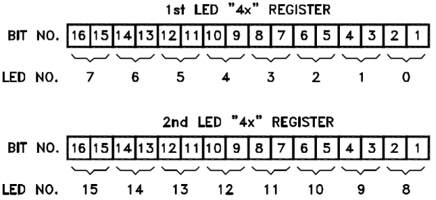
The registers start with number 40401 as mentioned previously and seen in the following register map spreadsheet information. The first registers in the sequence are always used to receive the basic or global panel information. If 1st LED 4x Register in the previous image represents register 40401, the bits would control the FSCS panel LEDs in the example system as follows:
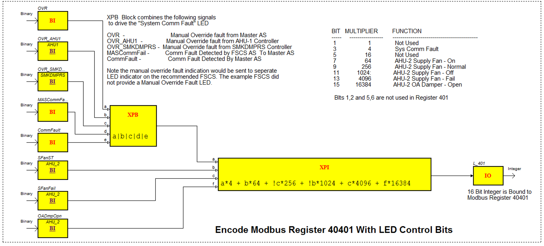
Bits 1 and 2 = FSCS Comm Fault LED
Bits 3 and 4 = System Comm Fault LED
Bits 5 and 6 = Sonalert (Horn)
Bits 7 and 8 = AHU-2 SupplyFan– On
Bits 9 and 10 = AHU-2 Supply Fan– Normal
Bits 11 and 12 = AHU-2 SupplyFan– Off
Bits 13 and 14 = AHU-2 Supply Fan– Fault
Bits 15 and 16 = AHU-2 OA Damper– Open
This LED to register position information is defined in the LED and Switch Mapping Spreadsheet which you generate with the help of Automation Displays. A portion of the LED and Switch Mapping file for the sample FSCS panel is shown here and is where you see the register 40401 example definitions shown previously.
It is suggested that additional LEDs be assigned to the base/core FSCS display functions (that is, the LEDs defined before you start assigning equipment such as the AHU-2 in the previous example). The recommended minimum set of system LED assignments includes the following:
|
Register |
Bits |
Description |
Color * |
|
40401 |
1 and 2 |
FSCS Comm Fault LED |
Amber/Orange |
|
40401 |
3 and 4 |
System Comm Fault LED |
Amber/Orange |
|
40401 |
5 and 6 |
Sonalert (Horn) |
|
|
40401 |
7 and 8 |
Equipment Fault LED ** |
Amber/Orange |
|
40401 |
9 and 10 |
Manual Override Fault LED*** |
Amber/Orange |
* The Amber/Orange LED colors suggested here provide compliance with Annex-H of the NFPA 92 2012 standard.
** The Equipment Fault LED is made to illuminate when any equipment faults are active on the panel.
*** The Manual Override Fault LED is made to illuminate when any smoke control controller is reporting an override switch that is in the manual position (on or off).
The example system uses only the Off and On (00 and 01) controls for the LEDs. The blinking control actions on the LEDs can optionally be used where applicable. For example, you may want to use a blink control on the equipment fault indicators to provide a quick FSCS indication where the Manual Override Fault is being detected. Such detail is optional on the FSCS and the workstation can be used to diagnose the location of such faults.
FSCS Switch Status Acquisition
The FSCS Z-Card transmits a PRESET 4X REGISTER (function code 10H) to the Smoke Control Server reporting the switch status to the 4X registers monitored by the program in the Smoke Control Server. When a switch is activated, a single bit is set in the corresponding register. Each 4X register holds sixteen bits, so sixteen switches are stored in each register. The FSCS panel maintains a memory image of all of the switches, so it is able to fill in all sixteen bits of the register, when only a single switch changes. Each switch requires a unique register bit address. The FSCS processor uses 4X register numbered 40001 through 40020 to represent switch contacts for a maximum of 320 switch contacts per Z-Card. The FSCS processor periodically refreshes all twenty of the 4X registers. When a switch is pressed, the message for that register is pushed to the front of the refresh queue for the fastest response.
The Switch registers present a bit per switch contact format as shown in this image:
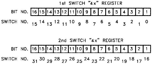
Bit Value 0= Switch Off
Bit Value 1= Switch On
One bit is used for each switch contact. Note that each switch may present more than one contact. Most of the switches in the example FSCS panel are single-pole-double-throw (SPDT) toggle switches with a center OFF (Auto) position. Each of those switches present two switch contacts. For example, one bit/contact for On, one bit/contact for Off and the Auto/center position indicated by a 0 bit indication on both the On and Off bit positions.
As described previously, the 4X Holding registers are used to pass information in both directions to and from the Smoke Control Server (AS-P/AS). The Registers 40001 to 40020 are used by the FSCS processor with the Modbus command/function code 10H to preset the switch states into the register contents in the Smoke Control Server. The register 40001 is always used, but the maximum register number will be determined by the number of switch contacts on the FSCS panel. The FSCS processor will poll the Smoke Control Server using the Modbus Command/Function code 03H to read the registers starting with 40401 to retrieve LED state information that was set into the registers by the Smoke Control Server application program.
The following tables present the LED and Switch to Modbus register mapping definition used on the example FSCS panel. The description, register number and bit numbers is the primary information you need to design your application program for the Smoke Control Server. The ADI ADR column is a sequential number of the LED displays or Switch controls provided on the panel. You may see that number used by ADI to reference the LED/Switch location on a graphic drawing of the panel used for your validation of the panel design. The IO Card column refers to the ADI I/O card in the panel used to drive the LED (or read the switch) and is not used in your application program. The Con/Pin column refers to the connector and pin where ADI is connecting the LED or switch and is also not applicable to your program application.
|
ADI ADR |
I/O Card |
Con/Pin |
Desc |
Color |
4x Reg |
Reg Bits |
|
0 |
L0 |
2/21 |
FSCS Comm Fault LED |
Amber |
401 |
1,2 |
|
1 |
L0 |
2/Y |
System Comm Fault LED |
Amber |
401 |
3,4 |
|
2 |
L0 |
2/20 |
Sonalert |
|
401 |
5,6 |
|
3 |
L0 |
2/X |
AHU–2 Supply Fan– On |
Green |
401 |
7,8 |
|
4 |
L0 |
2/19 |
AHU–2 Supply Fan– Normal |
White |
401 |
9,10 |
|
5 |
L0 |
2/W |
AHU–2 Supply Fan– Off |
Yellow |
401 |
11,12 |
|
6 |
L0 |
2/18 |
AHU–2 Supply Fan– Fault |
Amber |
401 |
13,14 |
|
7 |
L0 |
2/V |
AHU–2 OA Damper– Open |
Green |
401 |
15,16 |
|
8 |
L0 |
2/17 |
AHU–2 OA Damper– Normal |
White |
402 |
1,2 |
|
9 |
L0 |
2/U |
AHU–2 OA Damper– Closed |
Yellow |
402 |
3,4 |
|
10 |
L0 |
2/16 |
AHU–2 OA Damper– Fault |
Amber |
402 |
5,6 |
|
11 |
L0 |
2/T |
AHU–2 RA Damper– Open |
Green |
402 |
7,8 |
|
12 |
L0 |
2/15 |
AHU–2 RA Damper– Normal |
White |
402 |
9,10 |
|
13 |
L0 |
2/S |
AHU–2 RA Damper– Closed |
Yellow |
402 |
11,12 |
|
14 |
L0 |
2/14 |
AHU–2 RA Damper– Fault |
Amber |
402 |
13,14 |
|
15 |
L0 |
2/R |
AHU–2 EX Damper– Open |
Green |
402 |
15,16 |
|
16 |
L0 |
2/13 |
AHU–2 EX Damper– Normal |
White |
403 |
1,2 |
|
17 |
L0 |
2/P |
AHU–2 EX Damper– Closed |
Yellow |
403 |
3,4 |
|
18 |
L0 |
2/12 |
AHU–2 EX Damper– Fault |
Amber |
403 |
5,6 |
|
19 |
L0 |
2/N |
AHU–2 Return Fan– On |
Green |
403 |
7,8 |
|
20 |
L0 |
2/11 |
AHU–2 Return Fan– Normal |
White |
403 |
9,10 |
|
21 |
L0 |
2/M |
AHU–2 Return Fan– Off |
Yellow |
403 |
11,12 |
|
22 |
L0 |
2/10 |
AHU–2 Return Fan– Fault |
Amber |
403 |
13,14 |
|
23 |
L0 |
2/L |
AHU–1 Supply Fan– On |
Green |
403 |
15,16 |
|
24 |
L0 |
2/9 |
AHU–1 Supply Fan–Normal |
White |
404 |
1,2 |
|
25 |
L0 |
2/K |
AHU–1 Supply Fan– Off |
Yellow |
404 |
3,4 |
|
26 |
L0 |
2/8 |
AHU–1 Supply Fan– Fault |
Amber |
404 |
5,6 |
|
27 |
L0 |
2/J |
AHU–1 OA Damper– Open |
Green |
404 |
7,8 |
|
28 |
L0 |
2/7 |
AHU–1 OA Damper– Normal |
White |
404 |
9,10 |
|
29 |
L0 |
2/H |
AHU–1 OA Damper - Closed |
Yellow |
404 |
11,12 |
|
30 |
L0 |
2/6 |
AHU–1 OA Damper– Fault |
Amber |
404 |
13,14 |
|
31 |
L0 |
2/F |
AHU–1 RA Damper– Open |
Green |
404 |
15,16 |
|
32 |
L0 |
2/5 |
AHU–1 RA Damper– Normal |
White |
405 |
1,2 |
|
33 |
L0 |
2/E |
AHU–1 RA Damper– Closed |
Yellow |
405 |
3,4 |
|
34 |
L0 |
2/4 |
AHU–1 RA Damper– Fault |
Amber |
405 |
5,6 |
|
35 |
L0 |
2/D |
AHU–1 EX Damper– Open |
Green |
405 |
7,8 |
|
36 |
L0 |
2/3 |
AHU–1 EX Damper– Normal |
White |
405 |
9,10 |
|
37 |
L0 |
2/C |
AHU–1 EX Damper– Closed |
Yellow |
405 |
11,12 |
|
38 |
L0 |
2/2 |
AHU–1 EX Damper– Fault |
Amber |
405 |
13,14 |
|
39 |
L0 |
2/B |
AHU–1 Return Fan– On |
Green |
405 |
15,16 |
|
40 |
L0 |
1/21 |
AHU–1 Return Fan– Normal |
White |
406 |
1,2 |
|
41 |
L0 |
1/Y |
AHU–1 Return Fan– Off |
Yellow |
406 |
3,4 |
|
42 |
L0 |
1/20 |
AHU–1 Return Fan– Fault |
Amber |
406 |
5,6 |
|
43 |
L0 |
1/X |
4th Floor, SA Smoke Damper– Open |
Green |
406 |
7,8 |
|
44 |
L0 |
1/19 |
4th Floor, SA Smoke Damper - Normal |
White |
406 |
9,10 – |
|
45 |
L0 |
1/W |
4th Floor, SA Smoke Damper– Closed |
Yellow |
406 |
11,12 |
|
46 |
L0 |
1/18 |
4th Floor, SA Smoke Damper– Fault |
Amber |
406 |
13,14 |
|
47 |
L0 |
1/V |
4th Floor, RA Smoke Damper– Open |
Green |
406 |
15,16 |
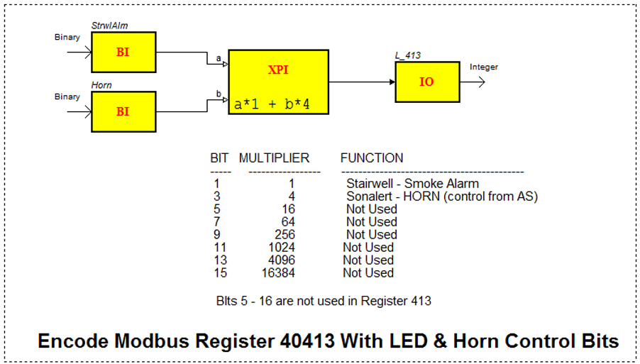
Register 40401 bits 1 and 2 are not used as these reference an LED only under direct control by the FSCS processor. Also, bits 5 and 6 reference the FSCS control of the sonalert (horn). The Smoke Control Server management of the horn is provided on register 40413 bits 3 and 4.
|
ADI ADR |
I/O Card |
Con/Pin |
Desc |
Color |
4X Reg |
Reg Bits |
|
48 |
L0 |
1/17 |
4th Floor, RA Smoke Damper– Normal |
White |
407 |
1,2 |
|
49 |
L0 |
1/U |
4th Floor, RA Smoke Damper– Closed |
Yellow |
407 |
3,4 |
|
50 |
L0 |
1/16 |
4th Floor, RA Smoke Damper– Fault |
Amber |
407 |
5,6 |
|
51 |
L0 |
1/T |
4th Floor, VAV Smoke Damper– Open |
Green |
407 |
7,8 |
|
52 |
L0 |
1/15 |
4th Floor, VAV Smoke Damper– Normal |
White |
407 |
9,10 |
|
53 |
L0 |
1/S |
4th Floor, VAV Smoke Damper– Closed |
Yellow |
407 |
11,12 |
|
54 |
L0 |
1/14 |
4th Floor, VAV Smoke Damper– Fault |
Amber |
407 |
13,14 |
|
55 |
L0 |
1/R |
Zone 4– Press |
Green |
407 |
15,16 |
|
56 |
L0 |
1/13 |
Zone 4– Exhaust |
Green |
408 |
1,2 |
|
57 |
L0 |
1/P |
Zone 4 Smoke Alarm |
Red |
408 |
3,4 |
|
58 |
L0 |
1/12 |
3rd Floor, SA Smoke Damper– Open |
Green |
408 |
5,6 |
|
59 |
L0 |
1/N |
3rd Floor, SA Smoke Damper– Normal |
White |
408 |
7,8 |
|
60 |
L0 |
1/11 |
3rd Floor, SA Smoke Damper– Closed |
Yellow |
408 |
9,10 |
|
61 |
L0 |
1/M |
3rd Floor, SA Smoke Damper– Fault |
Amber |
408 |
11,12 |
|
62 |
L0 |
1/10 |
3rd Floor, RA Smoke Damper– Open |
Green |
408 |
13,14 |
|
63 |
L0 |
1/L |
3rd Floor, RA Smoke Damper– Normal |
White |
408 |
15,16 |
|
64 |
L0 |
1/9 |
3rd Floor, RA Smoke Damper– Closed |
Yellow |
409 |
1,2 |
|
65 |
L0 |
1/K |
3rd Floor, RA Smoke Damper– Fault |
Amber |
409 |
3,4 |
|
66 |
L0 |
1/8 |
3rd Floor, VAV Smoke Damper– Open |
Green |
409 |
5,6 |
|
67 |
L0 |
1/J |
3rd Floor, VAV Smoke Damper– Normal |
White |
409 |
7,8 |
|
68 |
L0 |
1/7 |
3rd Floor, VAV Smoke Damper– Closed |
Yellow |
409 |
9,10 |
|
69 |
L0 |
1/H |
3rd Floor, VAV Smoke Damper– Fault |
Amber |
409 |
11,12 |
|
70 |
L0 |
1/6 |
Zone 3– Press |
Green |
409 |
13,14 |
|
71 |
L0 |
1/F |
Zone 3– Exhaust |
Green |
409 |
15, 16 |
|
72 |
L0 |
1/5 |
Zone 3 Smoke Alarm |
Red |
410 |
1,2 |
|
73 |
L0 |
1/E |
2nd Floor, SA Smoke Damper– Open |
Green |
410 |
3,4 |
|
74 |
L0 |
1/4 |
2nd Floor, SA Smoke Damper– Normal |
White |
410 |
5,6 |
|
75 |
L0 |
1/D |
2nd Floor, SA Smoke Damper– Closed |
Yellow |
410 |
7,8 |
|
76 |
L0 |
1/3 |
2nd Floor, SA Smoke Damper– Fault |
Amber |
410 |
9,10 |
|
77 |
L0 |
1/C |
2nd Floor, RA Smoke Damper– Open |
Green |
410 |
11,12 |
|
78 |
L0 |
1/2 |
2nd Floor, RA Smoke Damper– Normal |
White |
410 |
13,14 |
|
79 |
L0 |
1/B |
2nd Floor, RA Smoke Damper– Closed |
Yellow |
410 |
15,16 |
|
80 |
L1 |
2/21 |
2nd Floor, RA Smoke Damper– Fault |
Amber |
411 |
1,2 |
|
81 |
L1 |
2/Y |
2nd Floor, VAV Smoke Damper– Open |
Green |
411 |
3,4 |
|
82 |
L1 |
2/20 |
2nd Floor, VAV Smoke Damper– Normal |
White |
411 |
5,6 |
|
83 |
L1 |
2/X |
2nd Floor, VAV Smoke Damper– Closed |
Yellow |
411 |
7,8 |
|
84 |
L1 |
2/19 |
2nd Floor, VAV Smoke Damper– Fault |
Amber |
411 |
9,10 |
|
85 |
L1 |
2/W |
Zone 2– Press |
Green |
411 |
11,12 |
|
86 |
L1 |
2/18 |
Zone 2– Exhaust |
Green |
411 |
13,14 |
|
87 |
L1 |
2/V |
Zone 2 Smoke Alarm |
Red |
411 |
15,16 |
|
88 |
L1 |
2/17 |
1st Floor, Zone 1– Press |
Green |
412 |
1,2 |
|
89 |
L1 |
2/U |
1st Floor, Zone 1– Exhaust |
Green |
412 |
3,4 |
|
90 |
L1 |
2/16 |
Zone 1 Smoke Alarm |
Red |
412 |
5,6 |
|
91 |
L1 |
2/T |
AHU–3 Supply Fan– On |
Green |
412 |
7,8 |
|
92 |
L1 |
2/15 |
AHU–3 Supply Fan– Normal |
White |
412 |
9,10 |
|
93 |
L1 |
2/S |
AHU–3 Supply Fan– Off |
Yellow |
412 |
11,12 |
|
94 |
L1 |
2/14 |
AHU–3 Supply Fan– Fault |
Amber |
412 |
13,14 |
|
95 |
L1 |
2/R |
Stairwell– Press |
Green |
412 |
15,16 |
|
96 |
L1 |
2/13 |
Stairwell Smoke Alarm |
Red |
413 |
1,2 |
|
97 |
L1 |
2/P |
Addressable Sonalert |
|
413 |
3,4 |
|
98 |
L1 |
2/12 |
Spare |
|
413 |
5,6 |
|
99 |
L1 |
2/N |
Spare |
|
413 |
7,8 |
|
100 |
L1 |
2/11 |
Spare |
|
413 |
9,10 |
|
101 |
L1 |
2/M |
Spare |
|
413 |
11,12 |
|
102 |
L1 |
2/10 |
Spare |
|
413 |
13,14 |
|
103 |
L1 |
2/L |
Spare |
|
413 |
15,16 |
|
ADI ADR |
I/O Card |
Con/Pin |
Desc |
4X Reg |
Reg Bit |
|
0 |
S0 |
2/21 |
Clear Faults |
1 |
1 |
|
1 |
S0 |
2/Y |
Lamp Test |
1 |
2 |
|
2 |
S0 |
2/20 |
Panel Silence |
1 |
3 |
|
3 |
S0 |
2/X |
Panel Enable |
1 |
4 |
|
4 |
S0 |
2/19 |
AHU–2 Supply Fan– On |
1 |
5 |
|
5 |
S0 |
2/W |
AHU–2 Supply Fan– Off |
1 |
6 |
|
6 |
S0 |
2/18 |
AHU–2 OA Damper– Open |
1 |
7 |
|
7 |
S0 |
2/V |
AHU–2 OA Damper– Closed |
1 |
8 |
|
8 |
S0 |
2/17 |
AHU–2 RA Damper– Open |
1 |
9 |
|
9 |
S0 |
2/U |
AHU–2 RA Damper– Closed |
1 |
10 |
|
10 |
S0 |
2/16 |
AHU–2 EX Damper– Open |
1 |
11 |
|
11 |
S0 |
2/T |
AHU–2 EX Damper– Closed |
1 |
12 |
|
12 |
S0 |
2/15 |
AHU–2 Return Fan– On |
1 |
13 |
|
13 |
S0 |
2/S |
AHU–2 Return Fan– Off |
1 |
14 |
|
14 |
S0 |
2/14 |
AHU–1 Supply Fan– On |
1 |
15 |
|
15 |
S0 |
2/R |
AHU–1 Supply Fan– Off |
1 |
16 |
|
16 |
S0 |
2/13 |
AHU–1 OA Damper– Open |
2 |
1 |
|
17 |
S0 |
2/P |
AHU–1 OA Damper– Closed |
2 |
2 |
|
18 |
S0 |
2/12 |
AHU–1 RA Damper– Open |
2 |
3 |
|
19 |
S0 |
2/N |
AHU–1 RA Damper– Closed |
2 |
4 |
|
20 |
S0 |
2/11 |
AHU–1 EX Damper– Open |
2 |
5 |
|
21 |
S0 |
2/M |
AHU–1 EX Damper– Closed |
2 |
6 |
|
22 |
S0 |
2/10 |
AHU–1 Return Fan– On |
2 |
7 |
|
23 |
S0 |
2/L |
AHU–1 Return Fan– Off |
2 |
8 |
|
24 |
S0 |
2/9 |
4th Floor, SA Smoke Damper– Open |
2 |
9 |
|
25 |
S0 |
2/K |
4th Floor, SA Smoke Damper– Closed |
2 |
10 |
|
26 |
S0 |
2/8 |
4th Floor, RA Smoke Damper– Open |
2 |
11 |
|
27 |
S0 |
2/J |
4th Floor, RA Smoke Damper– Closed |
2 |
12 |
|
28 |
S0 |
2/7 |
Zone 4 VAV Damper– Open |
2 |
13 |
|
29 |
S0 |
2/H |
Zone 4 VAV Damper– Closed |
2 |
14 |
|
30 |
S0 |
2/6 |
Zone 4– Press |
2 |
15 |
|
31 |
S0 |
2/F |
Zone 4– Exhaust |
2 |
16 |
|
32 |
S0 |
2/5 |
3rd Floor, SA Smoke Damper– Open |
3 |
1 |
|
33 |
S0 |
2/E |
3rd Floor, SA Smoke Damper– Closed |
3 |
2 |
|
34 |
S0 |
2/4 |
3rd Floor, RA Smoke Damper– Open |
3 |
3 |
|
35 |
S0 |
2/D |
3rd Floor, RA Smoke Damper– Closed |
3 |
4 |
|
36 |
S0 |
2/3 |
Zone 3 VAV Damper– Open |
3 |
5 |
|
37 |
S0 |
2/C |
Zone 3 VAV Damper– Closed |
3 |
6 |
|
38 |
S0 |
2/2 |
Zone 3– Press |
3 |
7 |
|
39 |
S0 |
2/B |
Zone 3– Exhaust |
3 |
8 |
|
40 |
S0 |
1/21 |
2nd Floor, SA Smoke Damper - Open |
3 |
9 |
|
41 |
S0 |
1/Y |
2nd Floor, SA Smoke Damper– Closed |
3 |
10 |
|
42 |
S0 |
1/20 |
2nd Floor, RA Smoke Damper– Open |
3 |
11 |
|
43 |
S0 |
1/X |
2nd Floor, RA Smoke Damper– Closed |
3 |
12 |
|
44 |
S0 |
1/19 |
Zone 2 VAV Damper– Open |
3 |
13 |
|
45 |
S0 |
1/W |
Zone 2 VAV Damper– Closed |
3 |
14 |
|
46 |
S0 |
1/18 |
Zone 2– Press |
3 |
15 |
|
47 |
S0 |
1/V |
Zone 2– Exhaust |
3 |
16 |
|
48 |
S0 |
1/17 |
Zone 1– Press |
4 |
1 |
|
49 |
S0 |
1/U |
Zone 1– Exhaust |
4 |
2 |
|
50 |
S0 |
1/16 |
AHU–3 Supply Fan– On |
4 |
3 |
|
51 |
S0 |
1/T |
AHU–3 Supply Fan– Off |
4 |
4 |
|
52 |
S0 |
1/15 |
Stairwell– Press |
4 |
5 |
The following diagram presents an example of a Function Block program that encodes the contents of an integer bound to Modbus register 40401. Multiple faults are merged to create a single System Comm Fault LED indication, and the first of the equipment status bits (AHU-2 Supply Fan and Outside Damper) are encoded.
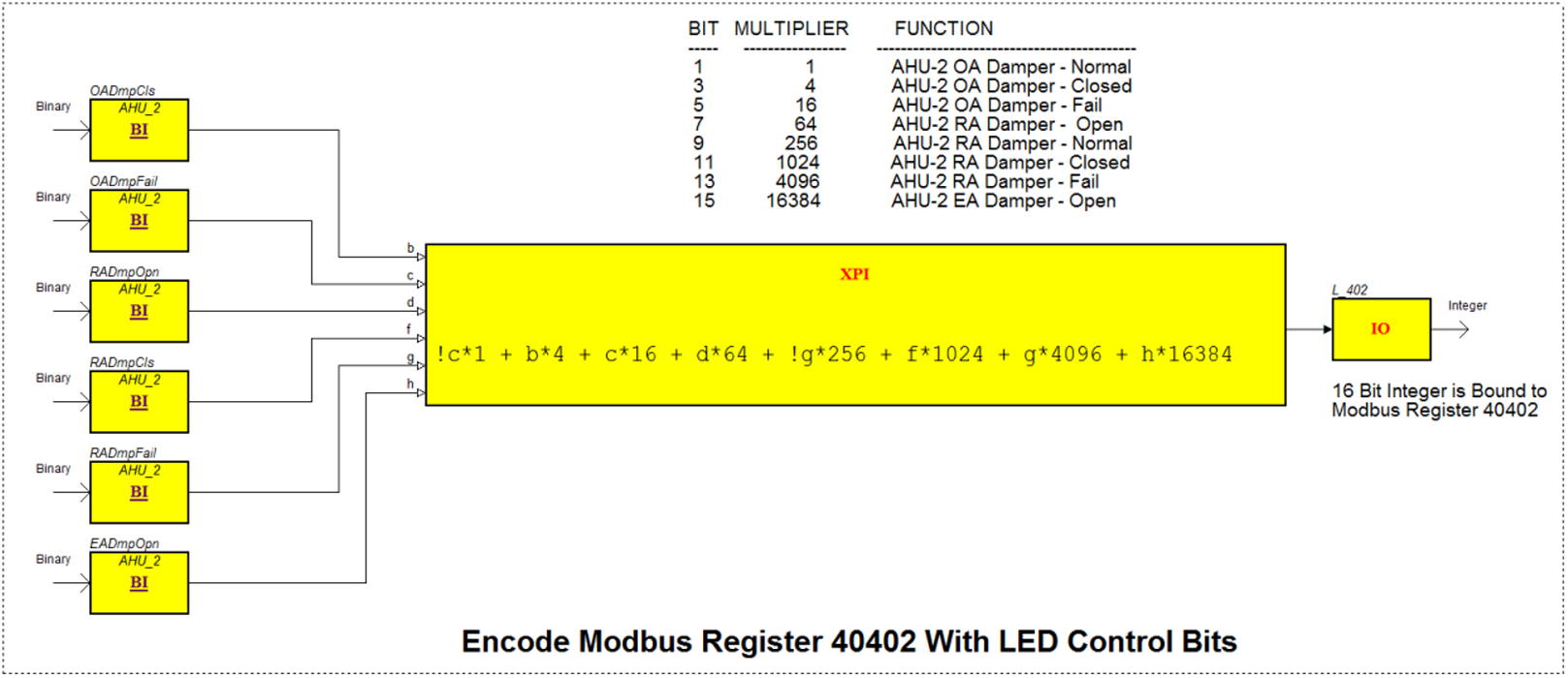
The following diagram presents the encoding of the next consecutive register 40102. Here, the integer is filled with the status bits for the next equipment elements (AHU-2 OA Damper, RA damper and the start of EA Damper).
The register encoding continues in a similar manner for the remaining equipment for Modbus registers 40403 to 40412.
The following Function Block program example is the last of the LED encode registers (number 40413). This register receives the bit indicating Alarm status in the Stairwell and the bit indicating Automation Server or AS-P control of the Sonalert or Horn.
FSCS Switch Decode
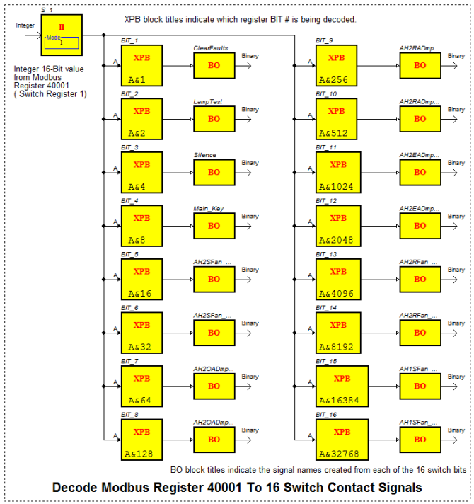
After encoding the FSCS LED data into the Modbus registers, the next task is the reverse where the switch FSCS states must be decoded from the Modbus registers. The FSCS will continuously update the Smoke Control Server managing the FSCS with the latest switch state information. Any change of states will prompt the FSCS to make the associated register be the next update transmission on the Modbus connection to the Smoke Control Server. As described previously, up to 16 switch contacts are packed by the FSCS into each register.
In the example Function Block programs, one page of logic is used to decode the integer contents (from the individual Modbus Register 40001 to 40004) and another page of logic is used to manage the enabling of the switch data and combine multiple bits into enumerated multi-state variables.
All of the FSCS Modbus switch registers are first decoded into up to 16 discrete signals and then, these signals are passed to the next page or program logic where multiple switch signals are used to create enumerated variables. This delivers one variable carrying the various command states for each piece of equipment.
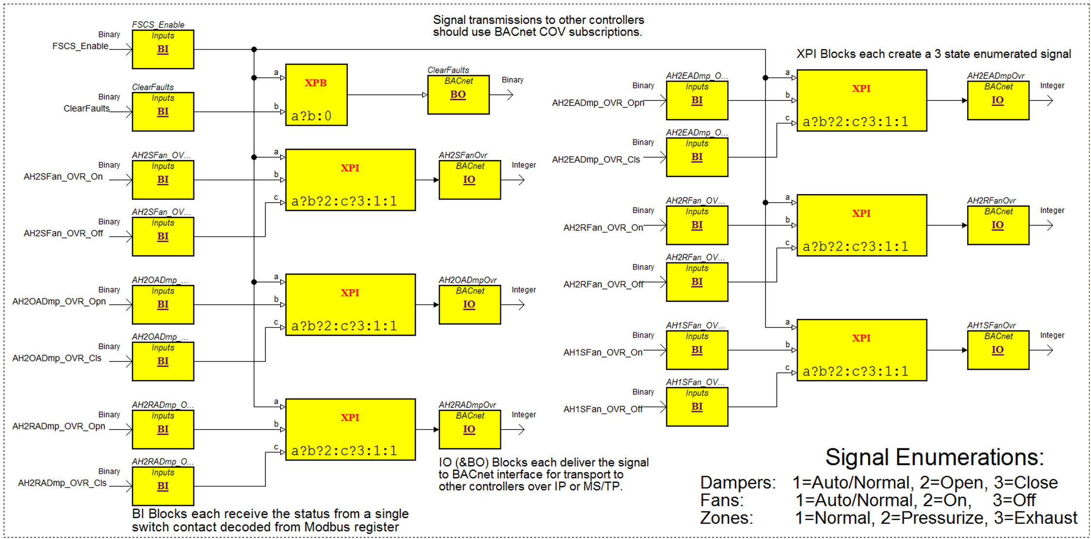
The FSCS_Enable signal from the key enable switch is used to enable the creation of each of the enumerated, override variables emitted from the FSCS. If the Key is turned to the disable position, ALL OVERRIDE VARIABLES go to the normal Auto value.
The following example Function Block program receives the first switch register S_1 (register 40001) and uses a sequence of XPBs performing a bitwise AND of each bit position to recover the 16 switch contacts encoded in the register value.
The following Function Block logic takes the individual switch contact signals decoded from the Modbus register (in logic above) and creates 3-state enumerated signals for each element of equipment. The enumerated signals are delivered to IO blocks for binding to BACnet value objects (which function as outputs) for transport to other controllers where the equipment override commands are used. This logic page also creates the binary output signal ClearFaults which is sent to other controllers where it is used to clear any latched faults resulting from weekly self-test functions.
The BO and IO output blocks in the following program are all bound to objects in the Application folder under BACnet Interface. This is to allow COV subscriptions from other Smoke Control Servers. The use of COV subscriptions is recommended for all smoke control application communications between Smoke Control Servers. Using I/E (Import/Export) is recommended for communications between the i2 controllers and their hosting server.
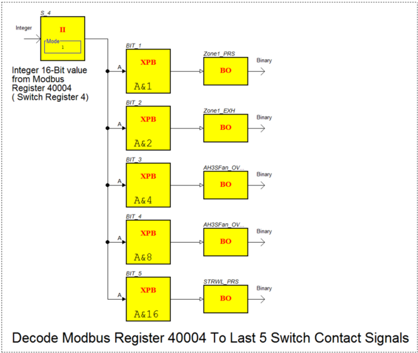
In the example system, switch registers S_2 and S_3 are each decoded and enumerated in the same manner with 8 enumerated signals from each used to override controller equipment.
The following figure shows the decoding of the last switch register S_4 (40004).
The following figure shows the last of the switch enumerations. The last item is an example of a two-state (ON and OFF) device that is always OFF under normal conditions and turned ON only for smoke control. It presents an enumeration of only 1 or 2 instead of the 1, 2 and 3 typical of the other equipment override controls.
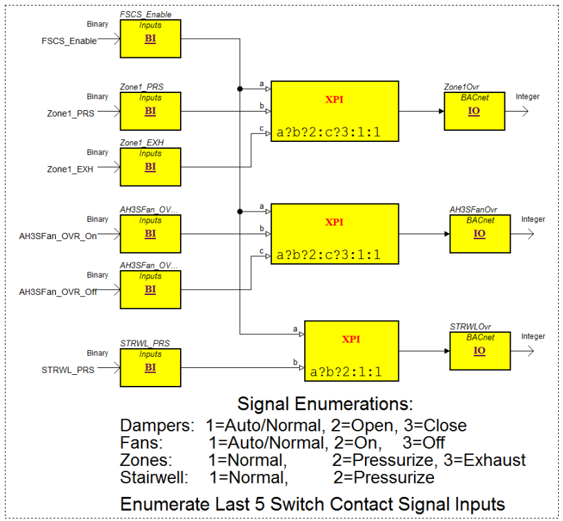
The use of BACnet multistate values is preferred for indicating the state of the equipment rather than analog values. The multistate value does prevent us from using the integer value of 0 as it is not an allowed state. The states start with 1 and increase in increments of 1 to the maximum state value that you define.
For i2 systems, using I/E is suggested for the exchange with the Supervising server where BACnet multistate is utilized for the FSCS Server exchange.
Horn Control
The following Function Block program presents an example of horn control for the FSCS panel. The 16 fault signals that will cause a horn activation come in from the left to the BI-Binary Input blocks. Each fault signal feeds an HFB (Hierarchical Function Block) whose logic contents are shown in the Horn HFB figure that follows. The outputs from all HFBs are logically ORed together by the XPB blocks and the result goes to the BO (Binary Output) block giving the Horn signal. The Horn signal goes to the L_413 Encode logic where the signal is encoded into a Modbus register (# 40413) that is retrieved by the FSCS and the bit causes the horn to activate.

When the user presses the Silence pushbutton (on a key-enabled FSCS), the Silence signal will activate and is presented as seen in the following figure. This generates the Mute signal that goes to each of the HFB blocks handling each of the fault sources.
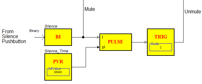
Within the HFB blocks, the Mute signal will extinguish the SignalOut feeding the XPB OR gates and therefore, silence the horn. The Mute also starts a 24-hour timer (86400 second Pulse). When that timer expires, the Unmut e signal is generated and goes to each of the HFB blocks which reactivates a silenced/muted horn if the fault signal is still active.
The figure that follows shows the logic inside each of the HFB blocks.
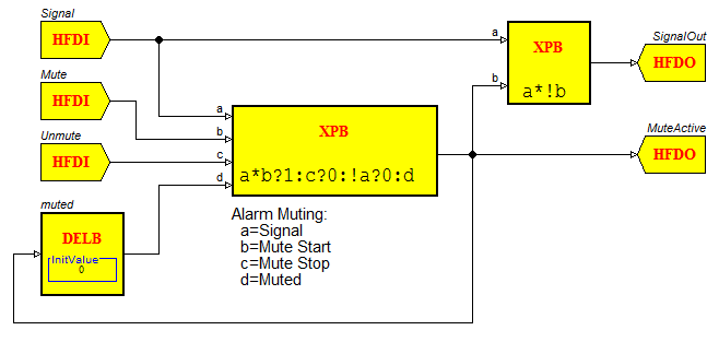
This HFB provides the following functions:
MuteActive output is set to 1 if the Mute input is active and the fault (Signal) is active.
When the momentary (pushbutton) Mute signal extinguishes, the MuteActive output remains true (1) due to the latching action of the HFB.
MuteActive output will be reset to 0 when the following occurs:
Unmute signal goes active
or
Fault Signal returns to the inactive 0 level
The following figure shows a signal timing/function diagram for the logic in the HFB block. The SignalOut output will follow the Signal (fault) input unless Mute is activated. Mute will cause the SignalOut to drop and Unmute returns the SignalOut active if the Signal (fault) input is active.

 FSCS Basics
 EcoStruxure BMS Smoke Control for BACnet MS/TP
 General Communications Conventions
 Fundamentals of Smoke Control
 FSCS Communication Status
 Equipment Fault Detection
 Weekly Self-Test