Concept
Equipment Fault Detection
Each controller managing smoke control equipment that is of sufficient size/importance to be displayed on the FSCS panel must also validate the operation of the equipment. When the equipment is non-dedicated, the normal HVAC applications will allow detection of equipment faults. The controller must use proofing sensors to confirm the fan is moving air, or the position of dampers has reached the intended position.
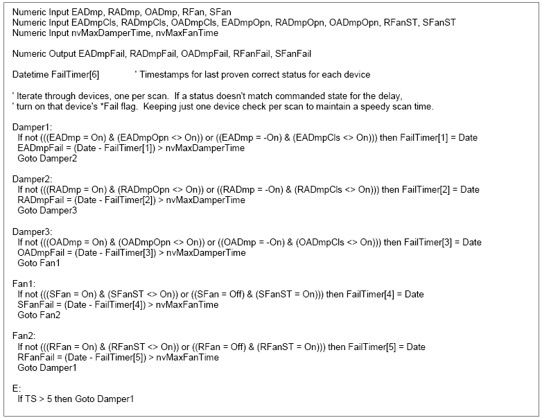
Shown here is a Script program example from the field controller (b3 or i2) for supervising the operation of three dampers and 2 fans. The example scheme uses an array of 6 timestamp values covering the 6 pieces of equipment monitored by the program. The timestamp value array represents the time each piece of equipment was last seen in the correct commanded state. The Damper 1 Script statement checks if the EA damper has been driven in the open direction or if it has been driven in the close direction. Depending if the damper was driven open and open proof is active (or it was driven closed and the closed proof is active), then the timestamp element is updated with the current time.

If the appropriate proof point for the commanded direction does not yet indicate the movement has been achieved, the timestamp array element will not be updated. When not updated, the array element timestamp continues to hold the time of the last correct position. This would be the time when the new direction movement started. The program next subtracts the timestamp element from the current time and compares the difference with the maximum damper time limit (nvMaxDamperTime). If the difference exceeds the limit, then the fail signal EADmpFail is set to 1 (true). The fail signal will reset to 0 when/if the damper later achieves the proof position.
The fail signal is routed to the FSCS Smoke Control Server where it is bound to the FSCS Logic going to the L_405_Encode program for display on the FSCS. On the next program scan, the next named line(s) will be executed. This will process one equipment element on each program scan. The following equipment elements are evaluated in the same manner as shown in the previous figure.
The smoke control applications in each of the controllers must monitor the state of any HOA override switches associated with an output used in the smoke control application. The status of the HOA switches are retrieved from the override switches and tested and as a minimum, a single override fault signal is sent to the FSCS for audible and visual fault indication.
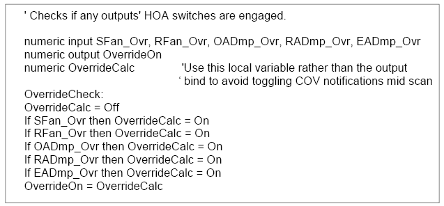
The Script program in the following figure presents an example of HOA switch supervision in a b3 controller (AHU_1 in example system). The input variables such as SFan_OVR have a binding to the Override property of the SFan object in the AHU_1 controller. The other xxxx_OVR inputs are bound to the Override property of their respectively named objects. The variable named OverrideOn is set to true if any of the 5 HOA override switches (handling the fans and dampers of AHI_1) are out of the Auto position. Other controllers with override switches are supervised with a similar program.

The OverrideOn variable here is exposed in the application folder of the AHU_1. The AHU_1 is learned into the FSCS Smoke Control Server and the OverrideOn value is bound to the FSCS Logic for the purposes of activating the horn and an LED.
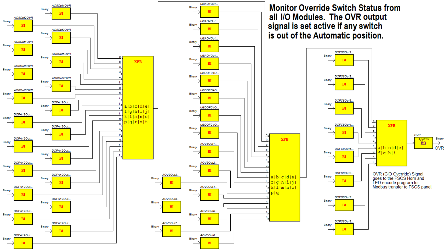
The Central IO modules extending from the Smoke Control Server may have the override switch option on the output type modules. Switches associated with outputs in the smoke control application must be supervised and produce an audible and visual fault indication if any switches are out of the automatic position.
The following figure shows the I/O switch supervision program in the example system. The OVR output is active 1 if any switch is out of AUTO position. OVR goes to the program seen in the LED Register 40402 Logic graphic for LED indication and the Horn Control Program for audible indication.
For more information, see Basic Application Functions .

 Basic Application Functions
 FSCS Communication Status