Concept
Terminal Base Installation
You must install EcoStruxure BMS modules within a cabinet/enclosure approved for UL 864 applications. Refer to the enclosure section for a list of the various models and sizes (or enclosure specifications) approved for the smoke control applications. For more information, see Smoke Control Enclosures and Requirements .
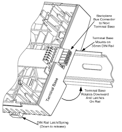
As seen in an earlier figure, the terminal base provides a connector plug protruding from the right side of the unit, along with a connector receptacle on its left side.
To create the contiguous I/O bus, the terminal base units simply slide together on the DIN rail with the plug inserting into the receptacle of the terminal base to the right. For example, a simple I/O bus is shown in the figure that follows with a PS- 24V, Automation Server (AS-SMK), or AS-P-SMK* or AS-P-NLS-SMK* (*not shown) and two Central IO modules.

All of the buses use a common ground which is connected to the signal return paths with terminals called RET. The signal return path is also called signal ground. The power bus distributes 24 VDC power from the power supply to the Smoke Control Server and all Central IO modules. The address bus is used to pass the address (position) from the terminal base backplane to the electronics module that is installed on the terminal base and to the next terminal base on the I/O bus.
The communication bus enables serial (RS-485) communication between the Smoke Control Server and the Central IO modules. The Smoke Control Server controls and supervises the communication on the communication bus. The Central IO modules also monitor their communication status. When a new Central IO module is configured and connected to the I/O bus, the Automation Server automatically detects the new device.
Ventilation slots are provided along the top and bottom of the terminal base units as seen in the previous figure.
Since the terminal base is separate from the Electronics Module, you can install and wire it long before the electronics module with the application program and data is supplied. You usually install the terminal base on a DIN rail, but you can also mount it directly on the wall. The electronics module is easily plugged in to the terminal base and firmly locked by pushing the handles in place. Replacing an electronics module is done in seconds since no terminal wiring is affected.

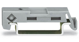
To prevent the modules from sliding sideways on the DIN rail, fix an end clamp for DIN 35 tightly against the rightmost device on the rail. The end clamp is easily removed if you bend the snap lock open with a screwdriver.

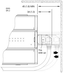
You can split the chain of devices on multiple DIN rails (rows) by using an extension cord called an S-cable. A maximum of five S-cables are allowed per system (collection of AS-P/AS Server and Central IO Modules). The S-cable connects the last (rightmost) device on one DIN rail with the first (leftmost) device on the next DIN rail. The complete chain of devices must remain within one cabinet for EMC reasons. The following figure shows an example of how you can use an S-cable to connect devices that are installed on separate DIN rails in a cabinet.

For proper cooling air flow through the devices, you should install the DIN rails and devices horizontally in the cabinet as shown. The S-cable provides right angle connectors on the ends and is available in two lengths:
1.5 meter length part number: SXWSCABLE10002
0.75 meter length part number: SXWSCABLE10003
Up to two S-cables can be serially connected to extend the length. The following graphic shows the minimum space required for plugging/unplugging the S-cable from the device. It also provides information on the minimum bend radius required to reduce the stress of the cable.

The order in which the devices are installed in the chain (I/O bus) is important. You should install the devices in the following order:
Position 1 (leftmost): Power supply (mandatory)
Position 2 Smoke Control Server (mandatory) ( Only One AS-P/AS Server per I/O Bus )
Position 3-32 Central IO modules and extra power supplies as needed based on power budget. One power supply can supply power for loads up to 30 W.
A maximum of 32 devices (counting PS-24V, Smoke Control Server and Central IO modules) can be attached on the bus.

 Power Rating
 PS-24V Power Supply Module
 Automation Server Installation
 AS-P and AS-P-NLS Installation
 Module and MP Controller Status LEDs