How to
Installing MP-V on a Damper that Rotates Clockwise (CW) to Open
You install the MP-V directly over the VAV damper shaft for damper positioning control and air flow sensing. When you install the MP-V on a damper that rotates clockwise (CW) to open, use WorkStation or the eCommission SmartX Controllers mobile application to ensure that the configured direction of the actuator rotation matches the damper type.
Refer to the dimensional drawing before installing the MP-V.
action_zoom_plus_stroke 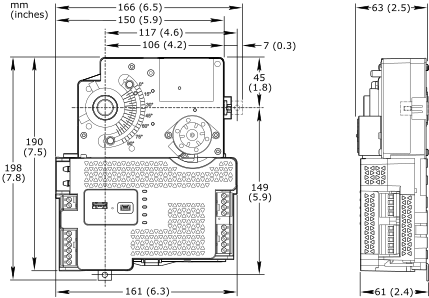
Ensure that the damper is of the type that opens by turning the damper shaft clockwise (CW).
action_zoom_plus_stroke 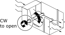
Determine the damper shaft length (L) and diameter (D).
action_zoom_plus_stroke 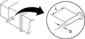
When the exposed damper shaft length (L) is less than 54 mm (2.125 inches) but greater than 22.2 mm (0.875 inch), move the two damper shaft mounting screws to the alternative screw holes for shorter damper shaft lengths.
For more information, see Moving the Damper Shaft Mounting Screws to the Alternative Positions for Short Shafts Only on MP-V .
When the damper shaft diameter (D) is equal to 9.5 mm (0.375 inch), install an AM-135 shaft adapter on the damper shaft.
For more information, see Installing an AM-135 Shaft Adapter on a 9.5 mm (0.375 inch) Diameter Damper Shaft .
Rotate the damper shaft to fully closed (CCW) position.
action_zoom_plus_stroke 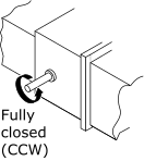
Press and hold the manual override button and rotate the actuator collar to fully closed (CCW) position.
action_zoom_plus_stroke 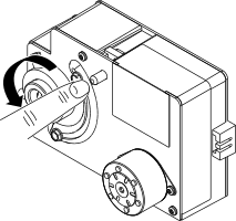
Release the manual override button. If necessary, rotate the actuator collar slightly to make the button return to the fully extended position.
Loosen the two damper shaft mounting screws using a 1/8-inch hex key and slide the controller over the damper shaft until the anti-rotation clip comes in close contact with the mounting area on the VAV box.
Important:When necessary due to mounting area restrictions or obstacles, the anti-rotation clip can be moved from the mounting bracket at the bottom of the controller (factory delivered location) to the mounting bracket on the side of the controller (alternative location).
action_zoom_plus_stroke 
To preload the damper for closed position, rotate the controller clockwise (CW) about three degrees or 10 mm (0.4 inch) off centerline of the damper.
action_zoom_plus_stroke 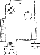
Tighten the two damper shaft mounting screws to the recommended torque using a torque wrench. For steel damper shafts, 6.8 to 7.9 Nm (60 to 70 lbf.in) is recommended. For aluminum damper shafts, 4.0 to 5.1 Nm (35 to 45 lbf.in) is recommended.
Important:When using the alternative positions for shorter damper shaft lengths, tighten the mounting screw that can be accessed, rotate the hub 90 degrees clockwise (CW) and tighten the other screw, then rotate the hub back 90 degrees counter-clockwise (CCW). Recommended screw tightening torque:
Steel damper shafts: 4.5 to 5.6 Nm (40 to 50 lbf.in)
Aluminum damper shafts: 4.0 to 5.1 Nm (35 to 45 lbf.in)
Important:When using an AM-135 shaft adapter, position the cutout section of the adapter cylinder to match the damper shaft mounting screw positions, before you tighten the screws against the damper shaft through the cutout section. Do not tighten the screws against the adapter cylinder.
action_zoom_plus_stroke 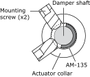
action_zoom_plus_stroke 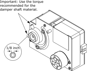
Rotate the controller counter-clockwise (CCW) back into alignment with the centerline of the damper. The damper should now be tightly closed.
action_zoom_plus_stroke 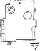
Using the controller's anti-rotation clip as a template, mark and drill a pilot hole in the VAV box.
Ensure the mounting hole position does not affect the performance of the VAV terminal unit. If the damper movement is affected, install the anti-rotation clip in the mounting bracket on the side of the controller (alternative location).
Secure the anti-rotation clip to the VAV box using a #10 self-tapping sheet metal screw.
action_zoom_plus_stroke 
Press and hold the manual override button and rotate the damper clockwise (CW) to fully open position by rotating the damper shaft.
action_zoom_plus_stroke 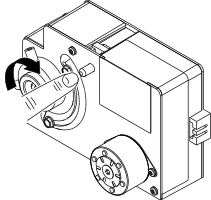
Release the manual override button. If necessary, rotate the actuator collar slightly to make the button return to the fully extended position.
Loosen the CW travel adjustment screw using a 1/4-inch hex key, slide the screw to the damper position indicator, and tighten the screw to 1.4 to 2.0 Nm (12 to 18 lbf.in) using a torque wrench.
Note:Loosen the screw only a quarter of a turn.
action_zoom_plus_stroke 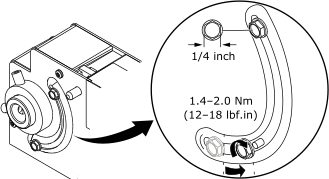
Verify that damper can rotate freely between the fully open and fully closed positions. There must be no binding between the actuator and damper, or obstructions hindering the damper operation.
action_zoom_plus_stroke 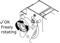
In WorkStation, ensure that Clockwise to open is the chosen direction of the actuator rotation to open the damper.
For more information, see Configuring MP-V Flow Balance Data .Note:With the eCommission SmartX Controllers mobile application, you can manually check the direction of the actuator rotation to verify that the actuator rotates clockwise (CW) to open the damper. For more information, see Manually Verifying the Direction of Damper Rotation .
 MP-V Device Installation
 Installing MP-V on a Damper that Rotates Counter-Clockwise (CCW) to Open
 Installing an AM-135 Shaft Adapter on a 9.5 mm (0.375 inch) Diameter Damper Shaft
 Moving the Damper Shaft Mounting Screws to the Alternative Positions for Short Shafts Only on MP-V
 Connecting an Air Velocity Probe to the MP-V Air Flow Sensor
 Installing a Terminal Block on MP-V
 Removing a Terminal Block from MP-V
 Wiring a Terminal Block on MP-V
 Powering Up MP-V
 Configuring MP-V Flow Balance Data
 Manually Verifying the Direction of Damper Rotation
 MP-V Damper Actuator Does Not Move or Respond to Position Commands


