Koncept
Grounding and Power for Systems with MP Controllers
This section provides grounding and power recommendations for system configurations with MP controllers.
Use the following recommendations to design a good working system:
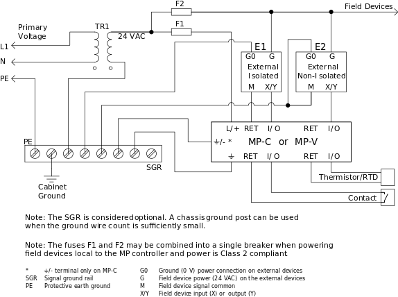
The Signal Ground Rail (SGR) shown in the diagram below is considered optional when the number of ground connections is small and ground connections can be achieved with a simple chassis ground post (a ground lug post suitable for the capacity is required). In a control panel application with many external non-isolated field devices, the SGR is recommended.
The return/common side of the transformer secondary, the ground symbol terminal on the MP controller, and the metal chassis/enclosure must be connected to a protective earth (PE) ground.
Connect the signal output (Y-terminals) from external devices such as transmitters to the universal inputs of the MP controller.
For isolated devices, connect the signal common from the transmitter to the corresponding RET pin on the same MP controller as the universal input.
For non-isolated devices, connect the signal common from the transmitter to the SGR in the panel.
Connect the signal input (X-terminals) of external devices such as actuators to the analog outputs (or MP-C universal outputs configured for analog output mode).
For isolated devices, connect the signal common from the actuator to the corresponding RET pin on the same MP controller as the analog output.
For non-isolated devices, connect the signal common from the actuator to the SGR in the panel.
Connect the G0 (Power Ground/Common) of external devices, such as actuators and transmitters, to the SGR in the panel.
Connect thermistors and dry contact devices to the universal input and corresponding RET terminal on the same MP controller as the universal input.
One or several 24 V power transformers can be used to supply the system.
When the MP-C is configured in large I/O applications with powered field devices, the power delivered to the field devices should be power limited (such as Class 2 for UL applications) with individual power limited transformers or fuses (circuit breakers) to limit circuit fault currents. Common signal ground wires share the sum of load currents for multiple connected devices and should be sized appropriately for the combined current.
When powering externally located field devices, use separate fuses (circuit breakers) for supplying power limited source to the MP controllers, rather than for connecting the power limited source to the field devices.
For UL listing compliance (Class 2 power), the fuses (circuit breakers) must be rated not more than 4A. For other regions that do not require UL compliance, fuses (circuit breakers) may be rated up to 6A.
For UL compliance, a UL Class 2 (100 VA or less) transformer may be used instead of the fuse/breaker limited transformer arrangement shown.
Fuses and circuit breakers must be sized appropriately to support the maximum rated controller power rating. Care must be taken when using fast-acting fuses or circuit breakers due to inrush currents on controller start-up due to input capacitance.

Powering more than one MP controller from a single transformer is acceptable when the controllers are installed within the same cabinet, or directly adjacent cabinets connected with conduit. When the controllers are separated in a facility, a separate 24 VAC step-down transformer is recommended to power each controller. The transformer with appropriate VA rating may also be used to power the locally connected I/O devices. The separate transformer helps to avoid problems with ground loops, 24 VAC induced EMI on LAN, low or distorted AC voltage level at the controller, and excess transformer load due to the half-wave power supply, which can result in intermittent equipment detected faults, loss of communications, or equipment damage. Because multiple MP-V controllers are never installed in the same cabinet or adjacent cabinets, all MP-V controllers are recommended to be powered by separate, local 24 VAC step-down transformers.
Distribution of 24 VAC from a central transformer to multiple separated MP controllers is not recommended. If you choose to use a central transformer, regardless of this recommendation, the installation of 24 V to 24 V isolation transformers at each controller is recommended to help avoid problems with ground loops. The use of isolation transformers does not help to avoid problems with 24 VAC induced EMI on LAN, low or distorted AC voltage level at the controller, and excess transformer load due to the half-wave power supply.
 I/O Wiring
 Grounding and Power
 MP-C Controllers
 MP-V Controllers