
Comment faire pour
Connecting RP Series Expansion Modules and Multi-sensors to RP-C
You connect RP Series expansion modules and multi-sensors to the RP-C room bus to provide the devices with power and communication from the RP-C controller.
The RP-C provides a room bus, which allows RP Series expansion modules and multi-sensors to be connected to the controller for motion detection, luminosity measurements, and control of electric lights and window blinds.
The maximum total length of the room bus is 72 m (236 ft). The room bus uses a Cat 5 (or higher) unshielded, straight-through wired cable with eight conductors (four twisted pairs) and RJ45 connectors. The wire size (cross-sectional area) should be 22 to 26 AWG (0.34 to 0.14 mm²). When the RP-C controller is installed in a space that handles conditioned air or return air, the room bus cables and IP network cables frequently must be plenum-rated to meet applicable building codes. Pour plus d'informations, voir Wiring .

You can connect a single RP Series expansion module or multi-sensor to the RP-C room bus port, or you can connect up to six devices in a daisy-chain configuration.
When connecting devices to the RP-C room bus through a daisy-chain configuration, it does not matter if the incoming and outgoing cables are connected to one or the other room bus port on the device.
The RP-C room bus supports up to six connected RP Series expansion modules and multi-sensors with the following restrictions:
Maximum of two DALI light modules
Maximum of two multi-sensors

Each RP Series expansion module and multi-sensor has a rotary switch, which is used to give the device a unique address on the room bus. An RP Series expansion module or multi-sensor can be given any address in the range of 1 to 6. Configuring the address 0 means that the device enters maintenance mode and goes offline. Configuring an address in the range of 7 to 9 also means that the device goes offline. Pour plus d'informations, voir RP Series Expansion Module Room Bus Addressing . An incorrectly configured switch can cause two devices to have the same address on the room bus, which means that both devices will be offline.
|
Address |
Description |
|
0 |
Maintenance mode. Device offline. |
|
1 to 6 |
Valid addresses supported by the EcoStruxure Building Operation software. |
|
7 to 9 |
Reserved for future use. Addresses not supported by the EcoStruxure Building Operation software. Device offline. |
Devices connected to the RP-C room bus through a daisy-chain configuration can be assigned addresses regardless of the order in which the devices appear in the daisy chain. For example, device number 1 can have the address 6, device number 2 can have the address 4, and so on.
An RP Series expansion module and multi-sensor can be put into different maintenance modes in which the device is either offline or online. Pour plus d'informations, voir RP Series Expansion Module and Multi-sensor Maintenance Modes .
Install the RP Series expansion module or multi-sensor and connect a Cat 5 (or higher) unshielded, straight-through wired cable with eight conductors (four twisted pairs) to one of the two RJ45 receptacles on the module or multi-sensor. Use a cable with the wire size (cross-sectional area) 22 to 26 AWG (0.34 to 0.14 mm²).
action_zoom_plus_stroke 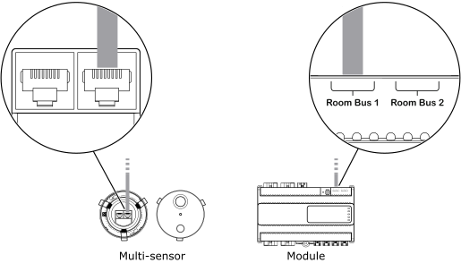
Connect the other end of the cable to the Room Bus port on the RP-C controller.
action_zoom_plus_stroke 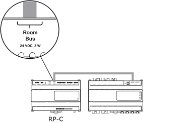
When an additional RP Series expansion module or multi-sensor is needed, install the device and connect the other end of the cable to the unused RJ45 receptacle on the previous module or multi-sensor.
DéclarationWhen connecting devices to the RP-C room bus through a daisy-chain configuration, it does not matter if the incoming and outgoing cables are connected to one or the other room bus port on the device.
action_zoom_plus_stroke 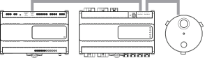
Repeat step 3 to install additional devices up to the maximum number of six devices of the supported combination of RP Series expansion modules and multi-sensors. Pour plus d'informations, voir RP-C Room Bus .
Ensure that the rotary switch on each RP Series expansion module and multi-sensor is configured to give the device a unique room bus address in the range of 1 to 6.
Pour plus d'informations, voir Configuring the Room Bus Address for an RP Series Expansion Module .
Pour plus d'informations, voir Configuring the Room Bus Address for an RP Series Expansion Multi-sensor .
Pour plus d'informations, voir RP Series Expansion Module Room Bus Addressing .
 RP-Cs
RP-C Room Bus
Configuring the Room Bus Address for an RP Series Expansion Module
Configuring the Room Bus Address for an RP Series Expansion Multi-sensor
RP Series Expansion Module Room Bus Addressing
RP-Cs
RP-C Room Bus
Configuring the Room Bus Address for an RP Series Expansion Module
Configuring the Room Bus Address for an RP Series Expansion Multi-sensor
RP Series Expansion Module Room Bus Addressing