Concept
Grounding and Power for Systems with RP-C 24 V Controller Models with Half-wave Rectified and Non-isolated Built-in Power Supply
This section provides grounding and power recommendations for system configurations with the RP-C controller models that support 24 VAC/VDC input power and have a half-wave rectified and non-isolated built-in power supply.
This applies to the following RP-C models with “-F” in the product name:
RP-C-12A-F-24V, RP-C-12B-F-24V, RP-C-12C-F-24V, and RP-C-16B-F-24V
For more information, see RP-C Models .
The recommended configuration is to use one local transformer for each RP-C controller (with its connected devices) to minimize any problems with ground loops and disturbances.
Use the following recommendations to design a good working system:
The fuse (circuit breaker) F11 must be rated 3 A or higher.
An external Signal Ground Rail (SGR) is not needed.
Every wire is an impedance, and current through an impedance results in a voltage that is proportional to the current. Such a voltage introduces disturbances to the signal. Thus:
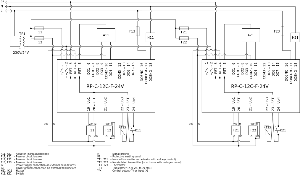
For external devices not internally connected to G0, use the corresponding RET connections rather than terminals 3, 4, or 5. This is according to T11, T13, and K11 in the figure below, and the reason is to help avoid high currents in the return cable which may result in noise.
For the return wires from external devices such as T13 and K11, use separate wires that are connected at the RET terminal.
Terminals 3, 4, and 5 together act as an internal ground rail that is internally connected to all local grounds such as RET and RS-485 (Room bus and Sensor bus) ground reference.

The fuses F11 and F12 may be combined into a single fuse (circuit breaker), but the recommendation is to use two separate fuses (circuit breakers).
It is important to know that several nodes are internally interconnected to the common signal ground. This is important for safety reasons and to help avoid ground loops and incorrect supply of G0. The following nodes are all interconnected:
All RET terminals (3, 4, 5, 20, 23, 26, and 29)
Antenna connector
USB connector shields
Ethernet network connector shields
RS-485 (Room bus and Sensor bus) ground reference
Terminal 2 (N/G0 input)
In case several RP-C controllers are supplied from one common 24 V transformer, terminal 2 is interconnecting all internal grounds for all RP-C controllers.
Powering more than one RP-C controller from a common transformer is acceptable when the controllers are installed within the same cabinet, or directly adjacent cabinets connected with conduit.
Use the following recommendations to design a good working system:
Use the same recommendations as provided for a system with a local transformer above.
Do not interconnect the RP-C controllers and their groups of connected devices, such as actuators and transmitters, beyond what is shown in the figure below to minimize potential problems with ground loops.
It is recommended to use separate fuses (circuit breakers), F11 and F21, for the power supply to each RP-C controller so that a problem with one RP-C controller does not affect another RP-C controller.
If you use a common fuse (circuit breaker) for two RP-C controllers, and there is a problem with one of the controllers, the troubleshooting may be more difficult.
It is recommended to use separate fuses (circuit breakers), F12 and F22, for the power supply to actuators and transmitters connected to different RP-C controllers so that a problem with an actuator or transmitter connected to one RP-C controller does not affect an actuator or transmitter connected to another RP-C controller.

 I/O Wiring
 Grounding and Power
 RP-C Controllers
 RP-C Models