
Spécifications
SpaceLogic RP-C-EXT-0-10V-4-PD

Introduction
SpaceLogic™ RP-C-EXT-0-10V-4-PD light module connects to the SpaceLogic RP room controllers and provides I/O expansion for 0-10V lighting control.
The 0-10V light module enables power supply and control of lights equipped with 0-10V ballasts.
Lighting can be controlled by the RP controller through motion detection and light intensity measurement provided by the Multi-sensor or Insight-Sensor, or by SpaceLogic Sensors connected to the RP controller.
The 0-10V light module is part of the RP controller expansion modules for connected room solution and can be combined with other modules from this product range.
Caractéristiques
Le module d’éclairage 1-10 V présente les caractéristiques suivantes :
Alimentation et communications via le bus "Room Bus"
Quatre sorties de commande d'éclairage (le nombre maximum d'éclairages par sortie est déterminé par le courant d'appel maximal)
Quatre entrées digitales pour la connexion d’interrupteurs d’éclairage et de contacts de fenêtre. Les entrées digitales répondent aux spécifications SELV (ultra-basse tension de sécurité).
Mesure de la consommation d’énergie par module
Adapté à un montage au plafond
Connecteurs Wieland pour une installation simple et rapide
Application mobile Engage permettant de configurer les paramètres de confort
LED d'état
Une LED d'état pour chaque sortie d'éclairage
Commutateur rotatif pour configuration d'adresse
Les sorties d'éclairage sont connectées au réseau d'alimentation via le module d'éclairage 0-10 V. Pour les câbles de commande du 0-10 V c.c., vous pouvez utiliser l'équipement d'installation standard autorisé pour les installations ELV (ultra-basse tension). Le signal de contrôle 0-10 V c.c. répond aux spécifications SELV (ultra-basse tension de sécurité).
Le module 0-10V présente les caractéristiques suivantes :
Contrôle indépendant de chacune des quatre sorties
Les éclairages présents sur chaque sortie appartiennent au même groupe et offrent ainsi l'avantage d'un contrôle simultané (même point de consigne MARCHE / ARRÊT / Variation).
L'alimentation des ballasts est coupée lorsque les éclairages sont éteints.
The RP controller room bus allows RP controller expansion modules to be connected to the controller for people counting, motion detection, luminosity and sound pressure level measurements, Bluetooth Low Energy based applications, and control of electric lights and window blinds.
The RP-C Pro and RP-C Pro Plus controller room bus supports up to nine connected RP controller expansion modules with the following restrictions:
Maximum of two DALI light modules
Maximum of two SMI blind modules
Maximum of seven Multi-sensor or Insight-Sensor devices
The RP-C Advanced controller room bus supports up to six connected RP controller expansion modules with the following restrictions:
Maximum of two DALI light modules
Maximum of two SMI blind modules
Maximum of four Multi-sensor or Insight-Sensor devices
The RP-V Advanced controller room bus supports up to four connected RP controller expansion modules with the following restrictions:
Maximum of one DALI light module
Maximum of one SMI blind module
Maximum of two Multi-sensor or Insight-Sensor devices
Maximum total length of the room bus is 72 m (236 ft).
The Engage mobile application enables control of room temperature, fan speed, lights, and blinds/shades directly from a smartphone. A user can manage these settings when the application is connected to the RP controller.
The Engage mobile application is free and available for download from Google Play and Apple App Store.
For more information, see the Engage Specification Sheet.
|
Produit |
Référence |
|
RP-C-EXT-0-10V-4-PD
|
SXWRE0104PD10001
|
|
DIN-RAIL-CLIP, DIN-rail end clip
package of 25 pieces
|
SXWDINEND10001
|
|
Mounting plate - RP controller expansion modules
package of 5 pieces
|
SXWREMPK510001
|
Spécifications
| Electrical | |
Nominal voltage
|
230 VAC
|
Operating voltage range
|
+/-10 %
|
Frequency
|
50/60 Hz
|
Maximum current consumption
|
10 A
|
Room bus power consumption
|
0.3 W (24 VDC)
|
Protection
|
Maximum 16 A external fuse (circuit breaker) is needed
|
Overvoltage category
|
III
|
| Environment | |
Ambient temperature, operating
|
0 to 50 °C (32 to 122 °F)
|
Ambient temperature, storage
|
-20 to +70 °C (-4 to +158 °F)
|
Humidity
|
20 to 90 % RH non-condensing
|
Pollution degree
|
2
|
| Material | |
Plastic flame rating
|
UL94 V-0
|
Ingress protection rating
|
IP 20
|
| Mechanical | |
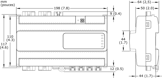
Dimensions
|
198 W x 110 H x 64 D mm (7.8 W x 4.3 H x 2.5 D in.)
|
|
|
Weight
|
0.418 kg (0.922 lb)
|
Recommended installation
|
DIN rail or flat surface in a cabinet
a
|
| a) It is recommended to install the device in an enclosure (cabinet), unless local regulations allow an exception. | |
Connectors
|
Power input: 1 x 3-pin Wieland GST15i3 connector
|
Light outputs: 4 x 5-pin Wieland GST15i5 connector
|
|
Digital inputs: 4 x 2-pin Wieland GST15i2 connector
|
|
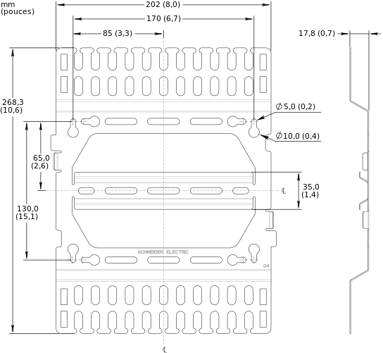
| Optional mounting plate | |
| The mounting plate is used to facilitate mounting and cable management for the RP controller expansion module as well as to provide strain relief for the connectors. | |
Dimensions
|
202 W x 268.3 H x 17.8 D mm (8.0 W x 10.6 H x 0.7 D in.)
|
|
|
Weight
|
0.306 kg (0.675 lb)
|
| Compatibility | |
EcoStruxure BMS server communication
|
|
EcoStruxure Building Operation
|
version 3.1.1 and later
|
Energy metering support
|
|
EcoStruxure Building Operation
|
version 3.3.1 and later
|
| Agency compliances | |
Emission
|
RCM; BS/EN 61000-6-3; BS/EN IEC 63044-5-2; FCC Part 15, Sub-part B, Class B
|
Immunity
|
BS/EN 61000-6-2; BS/EN IEC 63044-5-3
|
Safety standards
|
BS/EN 60730-1; BS/EN 60730-2-11; BS/EN IEC 63044-3
|
| Communication ports | |
Room bus
|
RS-485
|
Dual RJ45 ports for daisy-chain configurations
|
|
Use a Cat 5 (or higher) cable
|
|
Maximum total length of the room bus: 72 m (236 ft)
|
|
Room bus protection
|
Transient voltage suppressors on communication and power signals
|
| Hardware | |
CPU type
|
ARM Cortex-M4 single-core
|
Frequency
|
80 MHz
|
SRAM (embedded)
|
320 KB
|
Flash memory (embedded)
|
512 KB
|
NOR flash memory
|
16 MB
|
Status indicator
|
LED (green and red) that shows the status of the device
|
Light status indicator
|
One status LED (green) for each output
|
Address switch
|
Rotary switch 0 to 9
|
Set button
|
Push-button switch
|
| Energy metering | |
| Mesure de la consommation d'énergie | |
| The energy consumption is measured in Wh, shared by the four outputs. | |
Accuracy class (according to IEC 61557-12)
|
Active energy measurement: Class 1
|
Typical measurement accuracy at room temperature
|
20 to 100 W: 5%
|
100 to 3000 W: 1%
|
|
| 0-10V light outputs | |
Outputs
|
4, Light 1 to Light 4
|
Output terminals
|
N, PE, L, AOn (n: 1 to 4), and COM
|
Analog output voltage
|
0 to 10 VDC
|
Maximum source/sink current
|
10 mA per output
|
Power distribution
|
230 VAC (same voltage as power supply)
|
Maximum 5 A load per output
|
|
Maximum 10 A total load for the 4 outputs
|
|
Maximum 165 A inrush current (<20 ms) per output
|
|
Maximum 800 A inrush current (<200 µs) per output
|
|
| Digital inputs | |
Inputs
|
4, DI1 to DI4
|
Range
|
Dry contact, 0 to 5.0 VDC, 2.2 mA, SELV (Safety Extra-Low Voltage)
|
Connexions
Follow proper installation wiring diagrams and instructions. For more information on wiring, see the SpaceLogic and EasyLogic - Hardware Installation System Guide.

|
Use |
Part number |
Reference |
Connector type |
Suitable for cable diameters mm (inches) |
Marking |
Color of coding /housing |
Minimum order quantity |
|
Power supply input |
SXWRPCCONWWPOW |
91.931.4053.1 |
Female |
5.6–11 (0.22–0.43) |
L, PE, N |
Black /Black |
100 |
|
Light outputs |
SXWRPCCONWWLIGHTPD |
91.952.4453.0 |
Male |
8.5–12.5 (0.34–0.49) |
N, PE, L, D2, D1 D2: AO1..4 D1: COM |
Pastel blue /White |
50 |
|
Digital inputs |
SXWRPCCONWDI |
91.921.2353.0 |
Female |
3.4–5.5 (0.14–0.21) |
1, 2 1: DI1..4 2: RET |
Light blue /White |
100 |
The external connectors need to be ordered separately. The connectors can be ordered in quantities of 50 or 100 from Schneider Electric using the above part numbers. The connectors can also be ordered directly from Wieland using the above reference numbers. For more information, see the Wieland Electric web site.
SpaceLogic RP-C Advanced
SpaceLogic RP-C-EXT-MS-BLE
SpaceLogic RP-C-EXT-DALI-M-PD
SpaceLogic RP-C-EXT-BL-2-LV-PD
SpaceLogic RP-C-EXT-BL-4-HV-PD
SpaceLogic RP-C-EXT-BL-SMI-2-LV-PD
SpaceLogic RP-C-EXT-BL-SMI-4-HV-PD
SpaceLogic RP-C-EXT-DALI
SpaceLogic RP-C-EXT-0-10V-4
SpaceLogic RP-C-EXT-REL-4
Commission
Engage