How to
Installing an RP Controller Expansion Zigbee Module on a Ceiling
You install an RP controller expansion Zigbee module on a ceiling to properly fasten the device.
Refer to the dimensional drawings before installing the Zigbee module.
action_zoom_plus_stroke 
Ensure that you have the proper mounting hardware and anchoring system.
Check the weight-bearing load before choosing your mounting hardware.
Find a suitable location and surface on which to mount the Zigbee module.
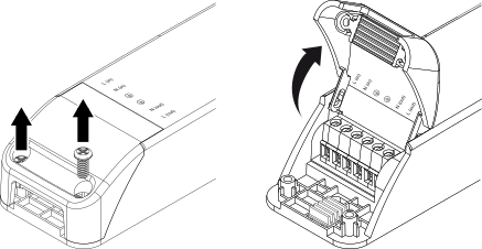
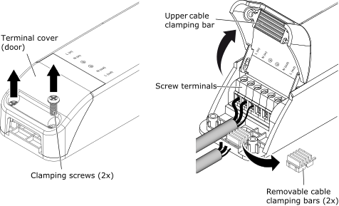
Loosen the screws that hold the two green terminal covers (doors) in place and then open the doors.
action_zoom_plus_stroke 
Hold the device in place against the ceiling.
Level the device.
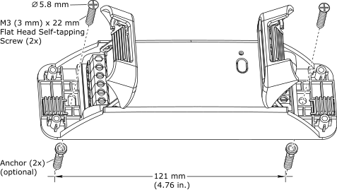
Mark the place where the two drill holes (for attachment of the device) should be on the ceiling.
The distance between the two holes is 121 mm (4.7 inches).
action_zoom_plus_stroke 
Remove the device.
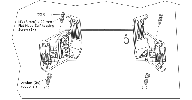
Drill two holes that fit M3 (3 mm) x 22 mm screws (or anchoring system per manufacturing specification).
Put the device in place on the ceiling and fasten the device using the two screws delivered with the device.
The device is delivered with two M3 (3 mm) x 22 mm Phillips flat head self-tapping screws with a 5.8 mm screw head diameter.
action_zoom_plus_stroke 
You can now wire the Zigbee module.
 Zigbee Modules Device Installation
 Wiring a Screw Terminal on an RP Controller Expansion Zigbee Module
 RP-C-EXT-ZB-DALI
 RP-C-EXT-ZB-0-10V
 Caution

 Danger
