Pojęcie
Relay Outputs on RP-C-EXT-REL-4
The RP-C-EXT-REL-4 relay module has four Relay outputs, which are designed for power supply and control of lights.
When a relay module is moved from one installation and reused in another installation, the module's “Cold start” and “System failure” values will be unknown. These values are stored in the module's persistent memory. The values control whether the relays will be on/active (energized) or off/inactive (de-energized) when the module is powered on (during a cold start) or powered off (due to a power outage). Connecting equipment to a relay module with unknown values on these properties entails a risk that the equipment will be damaged. To prevent this risk, the module's relay outputs need to be configured in EcoStruxure Building Operation WorkStation before connecting the equipment. This configuration means that the “Cold start” and “System failure” values for the module's Relay objects are configured to match the equipment to be connected. Więcej informacji zawiera Configuring Relays in the RP Controller Expansion Relay Module .
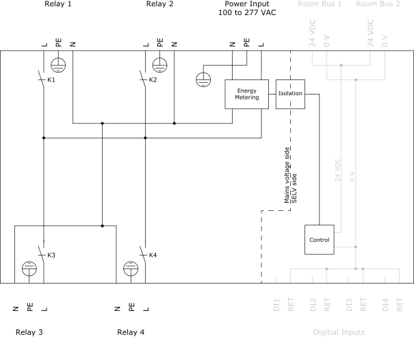
The relay module distributes the AC mains voltage (100 to 277 VAC) from the Power Input to the light control gear connected to the four Relay outputs.
The Relay output connector has three terminals for power distribution:
N (Neutral)
PE (Protective earth ground)
L (Line)

The four outputs are independently controlled. The relay module uses a relay to control the power distribution to each output, by connecting or disconnecting the AC mains voltage to the output (L terminal). In the figure above, the relay is named K1 for the Relay 1 output, K2 for the Relay 2 output, and so on.
The module's AC mains voltage side and low-voltage side (SELV side) are galvanically separated by means of isolation circuitry.
The maximum number of connected light control gear devices per module and per output is determined by the module's power distribution limitations. For more information, see section “Specifications”.
You can configure the module's “Cold start” and “System failure” values, which control whether the relays should be on/active (energized) or off/inactive (de-energized) under non-normal operating conditions such as when the module cold starts or loses communication with the RP-C controller. Więcej informacji zawiera Configuring Relays in the RP Controller Expansion Relay Module .
In the event of a power outage, the relays are set to the “System failure value”. When the power supply returns, the relays are temporarily set to the “Cold start value” before the relay module has all its properties reinforced by the parent RP-C controller. Więcej informacji zawiera RP Controller Expansion Relay Module Relay Properties - Basic Tab .
The module also has energy metering circuitry that supports the measurement of the energy consumption for the total load connected to the module. Więcej informacji zawiera RP Controller Expansion Module Energy Metering .
Dane techniczne
Outputs
|
4, Relay 1 to Relay 4
|
Output terminals
|
N, PE, and L
|
Power distribution
|
100 to 277 VAC (same voltage as power supply)
|
Maximum 5 A load per output
|
|
Maximum 10 A total load for the 4 outputs
|
|
Maximum 165 A inrush current (<20 ms) per output
|
|
Maximum 800 A inrush current (<200 µs) per output
|
 RP Controller Expansion Modules
 Light Modules
 RP-C-EXT-REL-4
 RP Controller Expansion Module Pluggable Connectors
 RP Controller Expansion Module Energy Metering
 Configuring Relays in the RP Controller Expansion Relay Module
 RP Controller Expansion Relay Module Relay Properties - Basic Tab