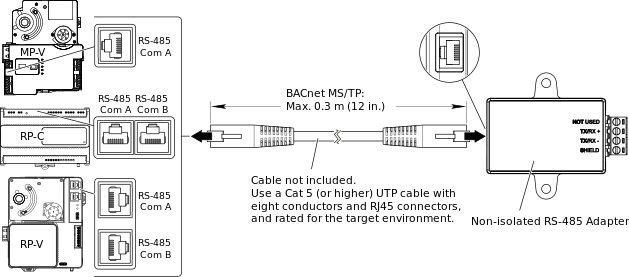
The Non-isolated RS-485 Adapter is equipped with an RJ45 port for connection to an RP or MP controller RS-485 Com port and a 4-position removable screw terminal block for connection to a BACnet MS/TP (RS-485) network or Modbus RTU (RS-485) subnetwork.
action_zoom_plus_stroke

Rysunek:
RJ45 port and screw terminals, Non-isolated RS-485 Adapter
Connection to a BACnet MS/TP network
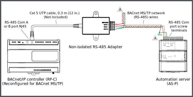
The following figure shows an example of how a Non-isolated RS-485 Adapter is connected to one of the RS-485 Com ports (RJ45) of an RP-C controller via a Cat 5 (or higher) UTP cable of maximum length 0.3 m (12 in.) and how the BACnet MS/TP network (RS-485) wires from the adapter are connected to the RS-485 Com port screw terminals of an AS-P server.
Follow the recommendations and guidelines for the RS-485 interface configuration in regard to data rate, biasing, termination, cable selection, cable length, and cable routing.
Więcej informacji zawiera RS-485 Communications
.
action_zoom_plus_stroke

Rysunek:
Example with a Non-isolated RS-485 Adapter used for connection of an RP-C controller to a BACnet MS/TP network and an AS-P server
action_zoom_plus_stroke

The BACnet MS/TP (RS-485) network should provide a 120 ohm termination resistor across the data pair (+ to -) at each end of the bus, that is, one 120 ohm termination resistor at the head end of the bus and a second 120 ohm termination resistor at the far end of the bus. Follow the recommendations and guidelines for the RS-485 interface configuration and guidance on when bias is required on the network (bias is not required for AS-P and AS-B servers, nor for RP and MP controller models with “-M” in the product name).
Więcej informacji zawiera
RS-485 Communications
.
Connection of RJ45 port to BACnet/IP controller RS-485 Com port
A separate connection cable is required to connect the RJ45 port on the RS-485 adapter to the RS-485 Com port (RJ45) on the BACnet/IP controller. The cable is not included and needs to be purchased separately.
Use a Cat 5 (or higher) unshielded, straight-through wired cable with eight conductors (four twisted pairs) and RJ45 connectors. Use a cable with the wire size (cross-sectional area) 22 to 26 AWG (0.34 to 0.14 mm²), a maximum length of 0.3 m (12 inches), and a rating that meets the requirements of the target environment. For example, when devices are installed in a space that handles conditioned air or return air, the cables typically need to be plenum-rated.
|
Uwaga
|
|
LOSS OF COMMUNICATION
Ensure that the length of the cable for connection of the RS-485 adapter to the controller does not exceed 0.3 m (12 inches).
Use a Cat 5 or higher unshielded twisted pair cable with eight conductors (four twisted pairs), a cross-sectional area of 22 to 26 AWG (0.34 to 0.14 mm
2
), and a rating that meets the requirements of the target environment.
Failure to follow these instructions can result in loss of communication.
|
Więcej informacji zawiera Connecting a Non-isolated RS-485 Adapter
.
Więcej informacji zawiera RJ45 Pinout for the RS-485 Port of the MP-V Controller
.
Więcej informacji zawiera RJ45 Pinout for the RS-485 Ports of the RP-C Controller
.
Więcej informacji zawiera RJ45 Pinout for the RS-485 Port(s) of the RP-V Controllers
.
Wiring of screw terminals for connection to BACnet MS/TP network
The four screw terminals are wired and connected to a BACnet MS/TP (RS-485) network as described in the following table.
Recommended screw tightening torque: 0.5 Nm (4.5 lbf.in)
Tabela: Screw Terminals, Non-isolated RS-485 Adapter
|
Terminal
|
Usage
|
|
NOT USED
|
Not connected.
|
|
TX/RX+
|
Data line (+) for connection to the TX/RX+ signal in the BACnet MS/TP twisted pair connecting all devices on the bus.
|
|
TX/RX–
|
Data line (–) for connection to the TX/RX– signal in the BACnet MS/TP twisted pair connecting all devices on the bus.
|
|
SHIELD
|
Convenience terminal to interconnect two shield drain wires (incoming and outgoing). There is no electrical connection in the device. The shield should be connected to ground at only one location and that is recommended to be at the automation server. The shield should not be connected directly to the RET terminal on the automation server. The transient energy on the drain wire should be conducted to ground and not through the automation server.
|
Więcej informacji zawiera Wiring the Screw Terminals on a Non-isolated RS-485 Adapter
.
Więcej informacji zawiera RS-485 Communications
.
Connection to a Modbus RTU subnetwork
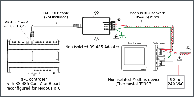
The following figure shows an example of how a Non-isolated RS-485 Adapter is connected to one of the RS-485 Com ports (RJ45) of an RP-C controller via a Cat 5 (or higher) UTP cable and how the Modbus RTU network twisted pair wires from the adapter are connected to the screw terminals of a Modbus device. In this example, the Modbus device is a thermostat from the SpaceLogic Thermostat TC907 Series. Additional Modbus devices may be daisy-chained from the thermostat.
Uwaga
The twisted pair cable used for TX/RX+ and TX/RX- data wires extends in one direction from the adapter to each device in a daisy chain bus configuration without cable stubs.
Follow the recommendations and guidelines for the RS-485 interface configuration in regard to data rate, biasing, termination, cable selection, cable length, and cable routing.
Więcej informacji zawiera RS-485 Communications
.
action_zoom_plus_stroke

Rysunek:
Example with a Non-isolated RS-485 Adapter used for connection of an RP-C controller to a Modbus RTU subnetwork and Modbus device(s)
action_zoom_plus_stroke

The Modbus (RS-485) network should provide a 120 ohm termination resistor across the data pair (+ to -) at each end of the bus, that is, one 120 ohm termination resistor at the head end of the bus and a second 120 ohm termination resistor at the far end of the bus. Follow the recommendations and guidelines for the RS-485 interface configuration and guidance on when bias is required on the network (bias is required when any Modbus devices on the bus are not of the Failsafe type).
Więcej informacji zawiera
RS-485 Communications
.
action_zoom_plus_stroke

The twisted pair shielded cable should only have the shield connected to ground at one location and that is the RP or MP controller. At each device, such as thermostat TC907, the shield drain wire from the incoming cable should be spliced to the shield drain wire of the outgoing cable and isolated from ground at each splice.
Connection of RJ45 port to RP or MP controller RS-485 Com port
A separate connection cable is required to connect the RJ45 port on the RS-485 adapter to the RS-485 Com port (RJ45) on the RP or MP controller. The cable is not included and needs to be purchased separately.
Use a Cat 5 (or higher) unshielded, straight-through wired cable with eight conductors (four twisted pairs) and RJ45 connectors. Use a cable with the wire size (cross-sectional area) 22 to 26 AWG (0.34 to 0.14 mm²), and a rating that meets the requirements of the target environment. For example, when devices are installed in a space that handles conditioned air or return air, the cables typically need to be plenum-rated.
|
Uwaga
|
|
LOSS OF COMMUNICATION
Use a Cat 5 or higher unshielded twisted pair cable with eight conductors (four twisted pairs), a cross-sectional area of 22 to 26 AWG (0.34 to 0.14 mm
2
), and a rating that meets the requirements of the target environment.
Failure to follow these instructions can result in loss of communication.
|
|
Uwaga
|
|
LOSS OF COMMUNICATION
Ensure that the total length of the RS-485 bus, from the controller to the end of the bus, does not exceed the recommended maximum cable length.
Więcej informacji zawiera RS-485 Communications
.
Failure to follow these instructions can result in loss of communication.
|
Więcej informacji zawiera Connecting a Non-isolated RS-485 Adapter
.
Więcej informacji zawiera Communication Port Wiring
.
Więcej informacji zawiera RJ45 Pinout for the RS-485 Port of the MP-V Controller
.
Więcej informacji zawiera RJ45 Pinout for the RS-485 Ports of the RP-C Controller
.
Więcej informacji zawiera RJ45 Pinout for the RS-485 Port(s) of the RP-V Controllers
.
Wiring of screw terminals for connection to Modbus subnetwork
The four screw terminals are wired and connected to a Modbus RTU (RS-485) subnetwork as described in the following table.
Recommended screw tightening torque: 0.5 Nm (4.5 lbf.in)
Tabela: Screw Terminals, Non-isolated RS-485 Adapter
|
Terminal
|
Usage
|
|
NOT USED
|
Not connected.
|
|
TX/RX+
|
Data line (+) for connection to the TX/RX+ signal in the Modbus RTU twisted pair connecting all devices on the bus.
|
|
TX/RX–
|
Data line (–) for connection to the TX/RX– signal in the Modbus RTU twisted pair connecting all devices on the bus.
|
|
SHIELD
|
Convenience terminal to interconnect two shield drain wires (incoming and outgoing). There is no electrical connection in the device. The shield should be connected to ground at only one location and that is recommended to be at the hosting RP or MP controller. The shield should be connected through to the next segment at each device without additional connections to ground. The shield should not be connected directly to the SHIELD terminal on the adapter. The transient energy on the drain wire should be conducted to ground and not through the adapter and on to the controller.
|
Więcej informacji zawiera Wiring the Screw Terminals on a Non-isolated RS-485 Adapter
.
Więcej informacji zawiera RS-485 Communications
.


 Non-isolated RS-485 Adapter Connection and Wiring
 RP-C BACnet MS/TP Support
 Allocating Flexible Ports
 Installing an RS-485 Adapter
 Wiring the Screw Terminals on a Non-isolated RS-485 Adapter


