Концепт
Convert a BACnet/IP Controller RS-485 Interface
The RS-485 Power Adapter can be used to convert a BACnet/IP controller (RP or MP controller) RS-485 interface from RJ45 port to screw terminals, which is required to be able to connect the controller to an RS-485 based network such as a Modbus RTU network. The types of RS-485-based networks supported differ between the different RP and MP controller models.
Through the RS-485 Power Adapter, 24 VDC can also be distributed from the BACnet/IP controller RS-485 interface to a device on the RS-485 bus.
You should not use the RS-485 Power Adapter to connect an MP or RP controller to a BACnet MS/TP (RS-485) network, even if there is nothing preventing you from physically connecting the adapter to such a network, as it can cause ground loops and poses a risk of miswiring of 24 VDC and bias terminals.
Examples
This section gives two examples of how the adapter can be used to convert an RP controller RS-485 interface:
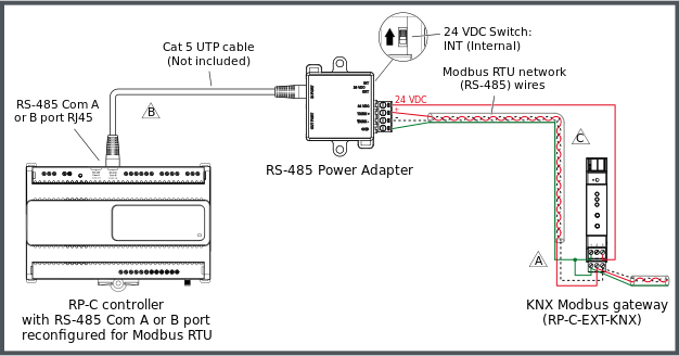
Example with an RP-C controller and a KNX Modbus gateway
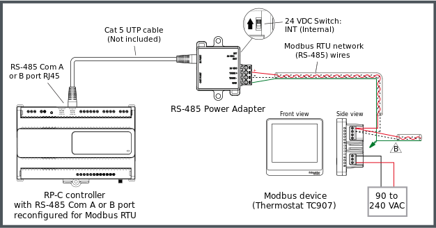
Example with an RP-C controller and a standard Modbus device
The RP controller Modbus network supports up to 10 connected Modbus devices with the following restrictions:
Maximum of one KNX Modbus gateway (RP-C-EXT-KNX)
Maximum of 250 Modbus registers per network
The following figure shows an example of how an RS-485 Power Adapter is connected to one of the RS-485 Com ports (RJ45) of an RP-C controller via a Cat 5 (or higher) UTP cable and how the Modbus RTU network twisted pair wires from the adapter are connected to the screw terminals of a KNX Modbus gateway (RP-C-EXT-KNX), which is powered by the controller via the adapter. Additional Modbus devices may be daisy-chained from the KNX Modbus gateway.
The twisted pair cable used for TX/RX+ and TX/RX- data wires extends in one direction from the adapter to each device in a daisy chain bus configuration without cable stubs.
Более подробную информацию см. KNX Modbus Gateway Screw Terminals and Connector .


The following figure shows an example of how the Modbus RTU network twisted pair wires from the adapter are connected to the screw terminals of a standard Modbus device, which is powered by a separate power supply. In this example, the Modbus device is a thermostat from the SpaceLogic Thermostat TC907 Series. Additional Modbus devices may be daisy-chained from the thermostat.
The twisted pair cable used for TX/RX+ and TX/RX- data wires extends in one direction from the adapter to each device in a daisy chain bus configuration without cable stubs.


Connection of RJ45 Port to BACnet/IP Controller RS-485 Com Port
A separate connection cable is required to connect the RJ45 port on the RS-485 Power Adapter to the RS-485 Com port (RJ45) on the BACnet/IP controller (RP or MP controller). The cable is not included and needs to be purchased separately.
Use a Cat 5 (or higher) unshielded, straight-through wired cable with eight conductors (four twisted pairs) and RJ45 connectors. Use a cable with the wire size (cross-sectional area) 22 to 26 AWG (0.34 to 0.14 mm²), and a rating that meets the requirements of the target environment. For example, when devices are installed in a space that handles conditioned air or return air, the cables typically need to be plenum-rated.
Более подробную информацию см. Connecting an RS-485 Power Adapter to Convert a BACnet/IP Controller RS-485 Interface .
Более подробную информацию см. Communication Port Wiring .
Более подробную информацию см. RJ45 Pinout for the RS-485 Port(s) of the RP-C Controllers .
Более подробную информацию см. RJ45 Pinout for the RS-485 Port(s) of the RP-V Controllers .
Более подробную информацию см. RJ45 Pinout for the RS-485 Port of the MP-V Controller .
Wiring of Screw Terminals for Connection to RS-485 Bus
The four screw terminals are wired and connected to an RS-485 bus as described in the following table.
Recommended screw tightening torque: 0.5 Nm (4.5 lbf.in)
|
Terminal |
Usage |
|
24 VDC |
Connected only when a device on the RS-485 bus requires 24 VDC power supply from the RP or MP controller. For example, the KNX Modbus gateway (RP-C-EXT-KNX) can be powered by an RP controller. Not connected in all other cases.
|
|
TX/RX+ |
Data line (+) for connection to the TX/RX+ signal in the RS-485 twisted pair connecting all devices on the RS-485 bus. |
|
TX/RX– |
Data line (–) for connection to the TX/RX– signal in the RS-485 twisted pair connecting all devices on the RS-485 bus. |
|
GND |
Ground terminal for connection to the signal ground and power ground of the controller. |
Более подробную информацию см. Wiring the Screw Terminals on an RS-485 Power Adapter for Connection to an RS-485 Bus .
Более подробную информацию см. RS-485 Communications .
 RS-485 Power Adapter
 RS-485 Power Adapter Ports, Terminals, and Switch
 Connecting an RS-485 Power Adapter to Convert a BACnet/IP Controller RS-485 Interface
 Communication Port Wiring
 RJ45 Pinout for the RS-485 Port(s) of the RP-C Controllers
 RJ45 Pinout for the RS-485 Port(s) of the RP-V Controllers
 RJ45 Pinout for the RS-485 Port of the MP-V Controller
 Wiring the Screw Terminals on an RS-485 Power Adapter for Connection to an RS-485 Bus
 KNX Modbus Gateway Screw Terminals and Connector
 Non-isolated RS-485 Adapter
 RS-485 Communications
 Enable Injection of 24 VDC from an External Power Supply to an RS-485 Bus
 RP-C Communication Ports
 Communication Ports on RP-C Models with “-F” in the Product Name
 Communication Ports on RP-V-4A and -5A
 RP-C Sensor Bus
 RP-V Sensor Bus
 MP-V Sensor Bus
 MP-C Sensor Bus
 RP-C Room Bus
 RP-V Room Bus
 RP-C Modbus
 RP-V Modbus
 MP-V Modbus
 Wiring
 Cable Selection