
Spécifications
EasyLogic RP-IO
Introduction
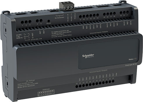
EasyLogic™ RP-IO module provides I/O expansion to your HVAC application over BACnet MS/TP. The I/O module can share its I/O resources across applications running in automation servers, RP and MP controllers, or third-party systems. With the support of local alarms and local trend logs, the I/O module avoids unnecessary traffic over the network while being able to log important information locally. The I/O module can be installed near facilities in the field, away from the automation server or the RP or MP controller.
The RP-IO has the following features:
Native BACnet MS/TP support
Full range of I/O module models
Versatile onboard I/O point mix
Built-in isolated power supply
Optional covers
Advanced monitoring
EasyLogic living space sensors
Full EcoStruxure Building Operation software support, providing efficient engineering tools
Upgrade with signed firmware
A maximum of three RP-IO modules can be used with an RP or MP controller. For more information, see the Architectural Guidelines.
Native BACnet MS/TP support
The EasyLogic range of RP and MP controllers and RP-IO I/O modules natively communicate with automation servers and field devices using the BACnet MS/TP protocol.
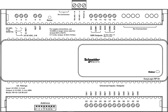
The RS-485 port with 3-pole screw terminal block is used for connection to the BACnet MS/TP network.
Full range of I/O module models
The EasyLogic RP-IO range of BACnet MS/TP based I/O modules includes two different models, which offer two different sets of I/O point types, named 12A and 16E. The two models support 24 VAC/DC power supply.

Models with a versatile mix of I/O points
The RP-IO-12A and -16E models provide 12 or 16 I/O points, consisting of two different sets of I/O point types. The versatile mix of I/O point types match a wide variety of applications. The universal inputs/outputs are highly flexible and can be configured as either inputs or outputs.
|
I/O Point Types |
RP-IO-12A model |
RP-IO-16E model |
|
Universal I/O Type Ub |
8 |
16 |
|
Solid-state relay outputs (MOSFET) |
4 |
- |
|
Configurations |
Universal I/O Type Ub |
Solid-state Relay Outputs (MOSFET) |
|
Digital inputs |
yes |
- |
|
Counter inputs |
yes |
- |
|
Supervised inputs |
yes |
- |
|
Voltage inputs (0 to 10 VDC) |
yes |
- |
|
Current inputs (0 to 20 mA) |
yes |
- |
|
Temperature inputs |
yes |
- |
|
Resistive inputs |
yes |
- |
|
Voltage outputs (0 to 10 VDC) |
yes |
- |
|
Digital outputs |
- |
yes |
|
Digital pulsed outputs |
- |
yes |
|
PWM outputs |
- |
yes |
|
Tristate outputs |
- |
yes |
|
Tristate pulsed outputs |
- |
yes |
The universal inputs/outputs are ideal for any mix of temperature, pressure, flow, status points, and similar point types in a building control system.
As counter inputs, the universal inputs/outputs are commonly used in energy metering applications. As supervised inputs, they are used for security applications where it is critical to know whether or not a wire has been cut or shorted. These events provide a separate indication of alarms and events in the system.
For all analog inputs, maximum and minimum levels can be defined to automatically detect over-range and under-range values.
The universal inputs/outputs are capable of supporting analog outputs of type voltage outputs. Therefore, the universal inputs/outputs support a wide range of devices, such as actuators.
Only devices with safe extra low voltage equipment (SELV/PELV) inputs/outputs should be connected to the universal inputs/outputs.
The solid-state relay (SSR) outputs can be used in many applications to switch 24 VAC or 24 VDC on or off for external loads such as actuators, relays, or indicators. SSRs are silent and are not adversely affected by relay contact wear.
Built-in isolated power supply
The device has a built-in power supply designed to accommodate 24 VAC or 24 VDC input power. The AC/DC power input is galvanically isolated from the electronics. This minimizes the risk of damage due to earth currents and permits the input power to be wired without concern for AC polarity matching. With the isolated AC/DC power input, you can use a central transformer for many devices, instead of one transformer for each device, to reduce installation costs.
Optional covers
All RP-IO models can be equipped with optional covers to reduce access to the screw terminals and wires.
Advanced monitoring
The I/O module supports local trends and alarms, enabling local operation when the I/O module is offline.
With user-defined fallback values, the I/O module outputs will be in a predictable state in cases of network disruption.
The battery-free power backup of the memory helps prevent data loss and allows seamless and quick recovery after a power disruption.
In WorkStation, you update the firmware of multiple I/O modules at the same time and with minimum down time. The EcoStruxure BMS server keeps track of the installed firmware to support backup, restore, and replacement of the I/O modules. The server can host I/O modules of different firmware versions.
EasyLogic living space sensors
The EasyLogic Sensor devices provide a cost-effective solution to measure, control, and communicate the temperature. The sensors are connected to analog inputs of the RP or MP controller. The EasyLogic Sensor devices are available in two models with different user interfaces, a blank cover or an LCD display with buttons for setpoint control. For more information, see the EasyLogic Sensors - Temperature Sensors – Analog - Specification Sheet.

Full EcoStruxure Building Operation software support
The power of the I/O module is fully realized when it is part of an EcoStruxure BMS, which provides the following benefits:
WorkStation/WebStation interface
Device discovery
Engineering efficiency
WorkStation and WebStation provide a consistent user experience regardless of which EcoStruxure BMS server the user is logged on to. The user can log on to the parent EcoStruxure BMS server to engineer, commission, supervise, and monitor the I/O modules and RP and MP controllers. For more information, see the WorkStation and WebStation specification sheets.
The enhanced Device Discovery in WorkStation enables you to easily identify the I/O modules on a BACnet network and to associate the I/O modules with their parent server.
The engineering and maintenance of the I/O modules can be done very efficiently using the EcoStruxure Building Operation reusability features. With these features, you can create library items (Custom Types) for a complete I/O module application that contains I/O point configurations and all necessary objects such as trends and alarms. The I/O module application in the Custom Types library is reusable across all I/O modules of the same model. You can use the I/O module application as a base for creating new I/O modules intended for similar applications. You can then edit the I/O module application, and the changes are automatically replicated to all I/O modules, while each I/O module keeps its local values.
WorkStation supports both online and offline engineering of the I/O modules. You can make the configuration changes online or use database mode to make the changes offline. In database mode, the changes are saved to the EcoStruxure Building Operation database so that you can apply the changes to the I/O modules later.
Project Configuration Tool enables you to perform all the engineering off site, without the need for physical hardware, which minimizes the time you need to spend on site. You can run the EcoStruxure BMS servers virtually and engineer the RP and MP controllers and the I/O modules before you deploy your server, controller, and I/O module applications to the servers, controllers, and I/O modules on site. For more information, see the Project Configuration Tool specification sheet.
Upgrade with signed firmware
Using digitally signed firmware provides more secure upgrading of the device. During an upgrade, the device verifies that the firmware is authentic and uncompromised Schneider Electric firmware. If the device detects discrepancies in the authenticity or integrity of the firmware, it will reject the upgrade. Once the device is upgraded with signed firmware, all upgrades thereafter must be with a signed firmware version.
|
Product |
Part number |
|
RP-IO-12A-M-24V
|
SXWRIOF12AM10001
|
|
RP-IO-16E-M-24V
|
SXWRIOF16EM10001
|
|
Product |
Part number |
|
Optional covers
|
SXWRPCCOV10001
|
|
DIN-RAIL-CLIP, DIN-rail end clip
package of 25 pieces
|
SXWDINEND10001
|
For more information on part numbers for Network Connectivity Accessories, see the Pour plus d'informations, voir Product Selection Guide - EcoStruxure Building ..
Spécifications
| AC input | |
Nominal voltage
|
24 VAC
|
Operating voltage range
|
+/-15 %
|
Frequency
|
50/60 Hz
|
Maximum power consumption
|
7 VA
|
Power input protection
|
MOV suppression and internal fuse
|
| DC input | |
Nominal voltage
|
24 to 30 VDC
|
Operating voltage range
|
21 to 33 VDC
|
Maximum power consumption
|
3 W
|
Power input protection
|
MOV suppression and internal fuse
|
| Environment | |
Ambient temperature, operating
|
0 to 50 °C (32 to 122 °F)
|
Ambient temperature, storage
|
-40 to +70 °C (-40 to +158 °F)
|
Maximum humidity
|
95 % RH non-condensing
|
| Material | |
Plastic flame rating
|
UL94 V-0
|
Ingress protection rating
|
IP 20
|
| Mechanical | |
Dimensions
|
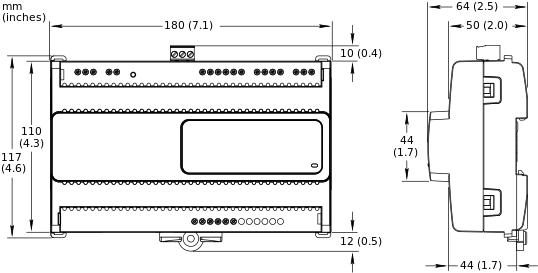
180 W x 110 H x 64 D mm (7.1 W x 4.3 H x 2.5 D in.)
|
|
|
Weight, RP-IO-12A-M-24V
|
0.336 kg (0.741 lb)
|
Weight, RP-IO-16E-M-24V
|
0.334 kg (0.736 lb)
|
Recommended installation
|
DIN rail or flat surface in a cabinet
a
|
| a) It is recommended to install the device in an enclosure (cabinet), unless local regulations allow an exception. | |
Terminal blocks
|
Power and I/O: Fixed
|
BACnet MS/TP communications: Removable
|
|
| Optional covers | |
Dimensions
|
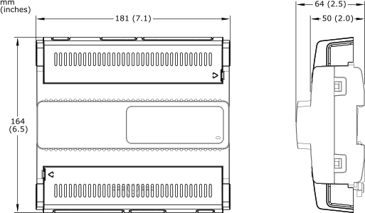
181 W x 164 H x 64 D mm (7.1 W x 6.5 H x 2.5 D in.)
|
|
|
Weight, optional covers
|
0.070 kg (0.154 lb)
|
| Compatibility | |
EcoStruxure BMS server communication
|
|
EcoStruxure Building Operation
|
version 5.0.1 and later
|
| Agency compliances | |
Emission
|
RCM; BS/EN 61000-6-3; BS/EN IEC 63044-5-2; FCC Part 15, Sub-part B, Class B
|
Immunity
|
BS/EN 61000-6-2; BS/EN IEC 63044-5-3
|
Safety standards
|
BS/EN 60730-1; BS/EN 60730-2-11; BS/EN IEC 63044-3; UL 916 C-UL US Listed
a
|
| a) The RP-IO-12A and -16E models are marked “Open Energy Management Equipment”. | |
Fire performance in air-handling spaces
a
|
UL 2043
|
| a) The RP-IO-12A and -16E models are approved for plenum applications. | |
| Communication ports | |
RS-485 port
|
RS-485 (3-pole screw terminal block)
|
Transient voltage suppressors on communication signals
|
|
| RS-485 transceiver characteristics | |
Transceiver type
|
Failsafe
|
Non-isolated
|
|
External biasing
|
None required
|
Total Unit Load (UL) per device
|
Maximum 0.5 UL
|
| Communications | |
BACnet
|
BACnet MS/TP, maximum bus length: 1200 m (4000 ft), maximum baud rate: 76800
|
BTL B-ASC (BACnet Application Specific Controller)
a
|
|
| a) See the BTL Product Catalog for up-to-date details on BTL listed firmware revisions on BACnet International's home page. | |
| CPU | |
Frequency
|
500 MHz
|
Type
|
ARM Cortex-A7 single-core
|
Internal SRAM
|
6 MB
|
NOR flash memory
|
32 MB
|
Memory backup
|
128 kB
a
, FRAM, non-volatile
|
| a) RP-IO-12A-M-24V with hardware version earlier than 01 and RP-IO-16E-M-24V with hardware version earlier than 03 have a FRAM memory with a size of 8 kB. For these hardware versions, the use of Script programs is recommended to save FRAM memory space. | |
| Universal inputs/outputs | |
Channels, RP-IO-12A-M-24V
|
8 Ub, Ub1 to Ub8
|
Channels, RP-IO-16E-M-24V
|
16 Ub, Ub1 to Ub16
|
Absolute maximum ratings
|
-0.5 to +24 VDC
|
A/D converter resolution
|
16 bits
|
Universal input/output protection
|
Transient voltage suppressor on each universal input/output
|
| Digital inputs | |
Range
|
Dry contact switch closure or open collector/open drain, 24 VDC, typical wetting current 2.4 mA
|
Minimum pulse width
|
150 ms
|
| Counter inputs | |
Range
|
Dry contact switch closure or open collector/open drain, 24 VDC, typical wetting current 2.4 mA
|
Minimum pulse width
|
20 ms
|
Maximum frequency
|
25 Hz
|
| Supervised inputs | |
5 V circuit, 1 or 2 resistors
|
|
Monitored switch combinations
|
Series only, parallel only, and series and parallel
|
Resistor range
|
1 to 10 kohm
|
| For a 2-resistor configuration, each resistor must have the same value +/- 5 % | |
| Voltage inputs | |
Range
|
0 to 10 VDC
|
Accuracy
|
+/-(7 mV + 0.2 % of reading)
|
Resolution
|
1.0 mV
|
Impedance
|
1 Mohm
|
| Current inputs | |
Range
|
0 to 20 mA
|
Accuracy
|
+/-(0.01 mA + 0.4 % of reading)
|
Resolution
|
1 μA
|
Impedance
|
47 ohm
|
| Resistive inputs | |
10 ohm to 10 kohm accuracy
|
+/-(7 + 4 x 10
-3
x R) ohm
|
| R = Resistance in ohm | |
10 kohm to 60 kohm accuracy
|
+/-(4 x 10
-3
x R + 7 x 10
-8
x R
2
) ohm
|
| R = Resistance in ohm | |
| Temperature inputs (thermistors) | |
Range
|
-50 to +150 °C (-58 to +302 °F)
|
| Supported thermistors | |
Honeywell
|
20 kohm
|
Type I (Continuum)
|
10 kohm
|
Type II (I/NET)
|
10 kohm
|
Type III (Satchwell)
|
10 kohm
|
Type IV (FD)
|
10 kohm
|
Type V (FD w/ 11k shunt)
|
Linearized 10 kohm
|
Satchwell D?T
|
Linearized 10 kohm
|
Johnson Controls
|
2.2 kohm
|
Xenta
|
1.8 kohm
|
Balco
|
1 kohm
|
| Measurement accuracy | |
20 kohm
|
-50 to -30 °C: +/-1.5 °C (-58 to -22 °F: +/-2.7 °F)
|
-30 to 0 °C: +/-0.5 °C (-22 to +32 °F: +/-0.9 °F)
|
|
0 to 100 °C: +/-0.2 °C (32 to 212 °F: +/-0.4 °F)
|
|
100 to 150 °C: +/-0.5 °C (212 to 302 °F: +/-0.9 °F)
|
|
10 kohm, 2.2 kohm, and 1.8 kohm
|
-50 to -30 °C: +/-0.75 °C (-58 to -22 °F: +/-1.35 °F)
|
-30 to +100 °C: +/-0.2 °C (-22 to +212 °F: +/-0.4 °F)
|
|
100 to 150 °C: +/-0.5 °C (212 to 302 °F: +/-0.9 °F)
|
|
Linearized 10 kohm
|
-50 to -30 °C: +/-2.0 °C (-58 to -22 °F: +/-3.6 °F)
|
-30 to 0 °C: +/-0.75 °C (-22 to +32 °F: +/-1.35 °F)
|
|
0 to 100 °C: +/-0.2 °C (32 to 212 °F: +/-0.4 °F)
|
|
100 to 150 °C: +/-0.5 °C (212 to 302 °F: +/-0.9 °F)
|
|
1 kohm
|
-50 to +150 °C: +/-1.0 °C (-58 to +302° F: +/-1.8 °F)
|
| Voltage outputs | |
Range
|
0 to 10 VDC
|
Accuracy
|
+/-60 mV
|
Resolution
|
10 mV
|
Minimum load resistance
|
2.4 kohm
|
Source current
|
+4.2 mA
|
Sink current
|
-1 mA (0 to 0.4 VDC)
|
-4.2 mA (0.4 to 10 VDC)
|
|
| Solid-state relay outputs, DO | |
Channels, RP-IO-12A-M-24V
|
4, DO1 to DO4
|
Channels, RP-IO-16E-M-24V
|
0
|
Output rating
|
Maximum 2 A load per output
|
Maximum 4 A total load for the 4 outputs
|
|
AC voltage range
|
Maximum 30 VAC
|
DC voltage range
|
Maximum 30 VDC
|
Commons
|
COM1 for DO1 and DO2 (on RP-IO-12A model)
|
COM2 for DO3 and DO4 (on RP-IO-12A model)
|
|
| When the SSR outputs are used to switch AC, the common terminals can be connected to 0 to 30 VAC. When the SSR outputs are used to switch DC, the common terminals can be connected to -30 VDC to +30 VDC. | |
Common voltage range (AC)
|
0 to 30 VAC
|
Common voltage range (DC)
|
-30 to +30 VDC
|
Minimum pulse width
|
100 ms
|
Solid-state relay output protection
|
Transient voltage suppressor across each solid-state relay (SSR) output
|
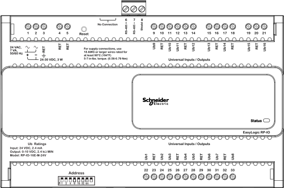
Terminals
For more information on wiring, see Hardware Reference Guide.
 Enterprise Server
 SpaceLogic AS-P
 SpaceLogic AS-B
 WorkStation
 WebStation
 Project Configuration Tool – Version 2