概念
Grounding and Power for Systems with RP-V Controllers
This section provides grounding and power recommendations for system configurations with the RP-V controllers, which support 24 VAC input power.
有关更多信息,请参阅 RP-V Controllers .
有关更多信息,请参阅 RP-V Built-in Isolated Power Supply .
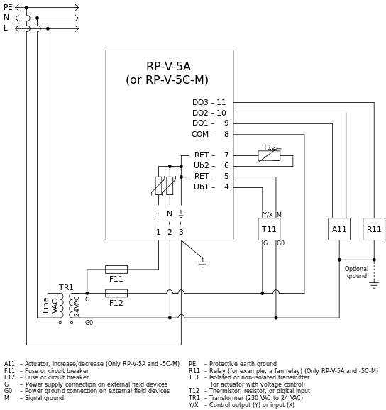
The recommended configuration is to use one local transformer for each RP-V controller (with its connected devices) to minimize any problems with ground loops and disturbances.
Use the following recommendations to design a good working system:
Connect the G0 (Power Ground/Common) of external devices, such as actuators and transmitters, to terminal 2.
Connect protective earth ground (PE) to terminal 3.
The fuse (circuit breaker) F11 must be rated 3 A or higher.

The fuses F11 and F12 may be combined into a single fuse (circuit breaker), but the recommendation is to use two separate fuses (circuit breakers).
It is important to know that several nodes are internally interconnected to the common signal ground. This is important for safety reasons and to help avoid ground loops and incorrect supply of G0, especially when these nodes are connected between different devices. The following nodes are all interconnected:
All RET terminals
RP-V-4A: Terminals 5, 8, 10 and 11
RP-V-5A: Terminals 5 and 7
RP-V-5C-M: Terminals 5 and 7
Antenna connector
USB connector shield
Ethernet network connector shields
RS-485 ground reference
Earth ground terminal 3
The connectors for external antenna, USB, and Ethernet are not available on RP-V-5C-M as this model does not support wireless connection or communication via USB or Ethernet.
Terminals 1 and 2 are internally isolated from everything else, but connected to common signal ground (RET) through Metal-oxide Varistors (MOVs) for protection reasons.
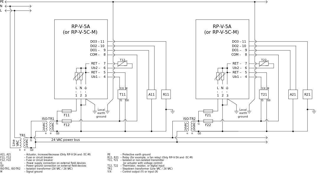
The built-in isolated power supply provided in the RP-V controller allows central transformer powering of multiple RP-V controllers. The RP-V controller can be grounded without affecting any of the 24 VAC power connections on terminals 1 and 2. A local isolated transformer is preferred, but a central transformer can be applied by following the recommendations below:
Important limitations and conditions for central transformer wiring:
Powering VAV boxes that have their fan or heating contactors, or valve actuators locally grounded creates ground loops with central transformer wiring, regardless of the isolation provided with the RP-V power input. These local grounding wiring arrangements must be avoided if central transformer wiring is used. Otherwise, it is recommended to use local isolated transformer powering of the RP-V controller and its local contactor or actuator loads.
When powering multiple RP-V controllers, the power output from the central transformer secondary side must be Class 2 power limited (100 VA or less).
The 24 VAC power wire size, length, and number of RP-V controllers and their accessory loads pulling power from the central transformer must be considered to maintain the 24 VAC voltage level at the most distant controller (from the transformer) well above the minimum level. The maximum expected load at each RP-V controller should be used to confirm the maximum expected voltage drop through the 24 VAC power conductors. A low 24 VAC level will cause spurious resets of the controller and may cause other unexpected behavior.
The RP-V controller uses a full-wave rectifier providing a higher transformer utilization factor. This allows the RP-V power rating (VA rating) to be broken down into the reduced component/function power levels. When larger power functions of the controller are not being used, these smaller RP-V power ratings along with the load of accessory devices can be used and accumulated to determine the number of devices that can be supplied from a central transformer. This is expected to primarily apply to cooling only VAV and other applications where there is no fan or other line powered loads. Most transformer manufacturers recommend a maximum power load (VA) of 80% of the transformer rating.
It is described for a system with a local transformer above that the RP-V terminal 2 can optionally be connected to local ground. This is not the case when the RP-V controllers are powered in a central transformer configuration. With central transformer wiring, the power input terminals must not be locally grounded. One of the connections of the central transformer secondary side can be connected to ground at the transformer. This is sometimes required by codes and standards for electrical wiring.
It is understood that central transformer wiring is desirable to apply lower cost and more flexible installation techniques. However, running low voltage power lines to the controllers does not eliminate the need for separation between the communications bus serving the controllers and the power lines serving the controllers. The standard minimum separation recommended by Schneider Electric is 457 mm (18 inches).
Be aware about the information about internal RET connections as provided for a system with a local transformer above.
Use the same recommendations regarding fuse (circuit breaker) ratings as provided for a system with a local transformer above.
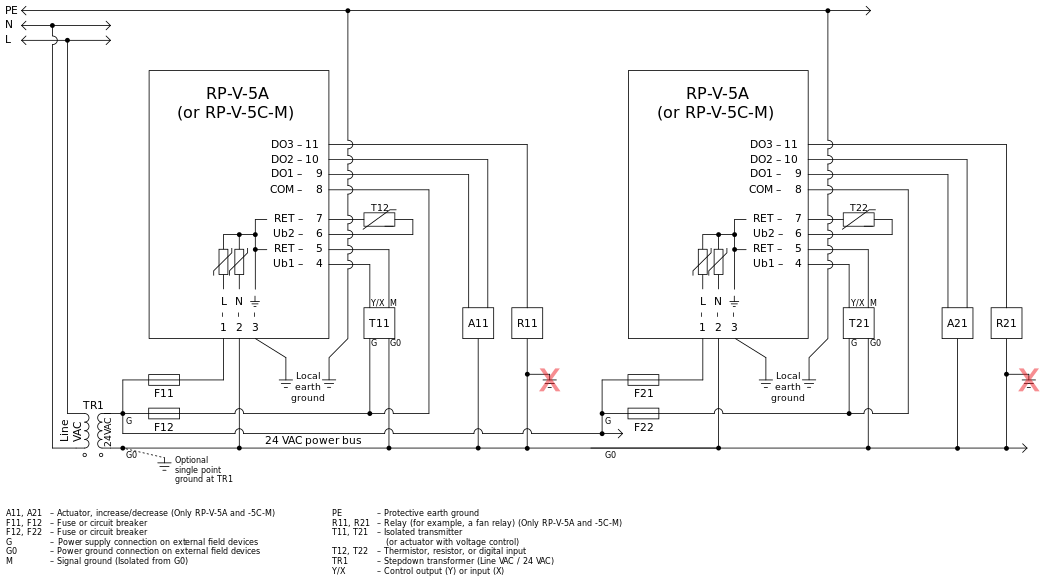
Do not interconnect the RP-V controllers and their groups of connected devices, such as actuators and transmitters, beyond what is shown in the figure below to minimize potential problems with ground loops.
It is recommended to use separate fuses (circuit breakers), F11 and F21, for the power supply to each RP-V controller so that a problem with one RP-V controller does not affect another RP-V controller.
If you use a common fuse (circuit breaker) for two RP-V controllers, and there is a problem with one of the controllers, the troubleshooting may be more difficult.
It is recommended to use separate fuses (circuit breakers), F12 and F22, for the power supply to actuators and transmitters connected to different RP-V controllers so that a problem with an actuator or transmitter connected to one RP-V controller does not affect an actuator or transmitter connected to another RP-V controller.
Unlike RP-V-4A and RP-V-5A, which use BACnet/IP (Ethernet), the RP-V-5C-M model uses BACnet MS/TP for communication over an RS-485 bus. Use the following recommendations to configure the RS-485 electrical interface between the controllers and the automation server that hosts the MS/TP (RS-485) bus and the controllers.
Proper communication on the BACnet MS/TP (RS-485) bus between controllers and the automation server is dependent on a common ground reference at each device. The common reference must not differ from the other MS/TP devices by an amount that exceeds the common-mode voltage tolerance of the RS-485 transceivers. The ground connection to terminal 3 is dependent on providing a solid ground path for transient suppression, but also to help avoid common-mode voltage differences between controllers and also the automation server that hosts the controllers. A difference of 0 volt is preferred but a difference of less than +/- 1 or 2 volts is needed. The shielded twisted pair cable used for the MS/TP (RS-485) bus is recommended to have the shield connected to earth ground at only one location and that connection is recommended to be at the automation server hosting the MS/TP (RS-485) bus. The shield should be spliced through at each controller location using the Shield convenience terminal. This shield offers a good reference to measure any ground voltage differences at each MS/TP node. Using the MS/TP cable shield as the reference, measure the voltage seen on the controller (terminal 3 or RET) to determine the ground difference from the MS/TP (RS-485) bus. 有关更多信息,请参阅 RS-485 Communications .
The Shield terminal on the controller's RS-485 terminal block is a convenience terminal intended to be used to interconnect two shield drain wires. There is no electrical connection in the controller.
The “N” (Neutral) power connection conductor for the 24 VAC power must not be connected to ground at controller locations distanced from the transformer. Avoid controlled devices creating a connection to ground (such as the red “X” below). When a ground is needed, it should be located at the transformer.

The following figure shows the wiring configuration, in accordance with the recommendations listed above, when the following requirements and situations are encountered:
Use of a central/common transformer is required.
The central 24 VAC is required to power external actuators or transmitters controlled or monitored by the RP-V controller.
The external actuators or transmitters are not isolated.
This means that the DC input/output signal does not provide an isolated “M” (signal common) terminal, but is referenced to one leg of the AC power (such as the G0 terminal) being used as the DC common.

 I/O Wiring
 Grounding and Power
 RP-V Controllers
 RP-V Built-in Isolated Power Supply
 RP-V Models
 RS-485 Communications