The RP-IO module can be installed on a DIN rail or other flat surface inside a cabinet. The device is recommended to be installed in a cabinet, unless local regulations allow an exception.
Installation orientations
Under normal operating conditions of 0 to 50 °C (32 to 122 °F), the RP-IO module can be installed in the following orientations:
Horizontally (on a DIN rail going from left to right), with the device label text in the upright position reading left to right. See “a” in the following figure.
Vertically (on a DIN rail going from top to bottom), which means that the device is rotated +90 degrees or -90 degrees from the horizontal position. See “b” and “c” in the following figure.
Face down from a ceiling. See “d” in the following figure.
Up and down, which means that the device is rotated 180 degrees from the horizontal position and with the device label text up and down. See “e” in the following figure.
Face up on a horizontal surface. See “f” in the following figure.
action_zoom_plus_stroke

Figura:
Installation orientations for the RP-IO module models operated in normal conditions, 0 to 50 °C (32 to 122 °F)
Installation on a DIN rail
A DIN rail is a common and convenient technique for installing the RP-IO module along with other associated control and monitoring devices. The most efficient ventilation is achieved with the wall-mounted DIN rail oriented horizontally and with adequate space provided between the RP-IO rail and adjacent rails or other devices.
The RP-IO module is typically installed horizontally (on a DIN rail going from left to right), with the device label text in the upright position reading left to right.
action_zoom_plus_stroke
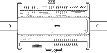
Figura:
Example of an RP-IO module installed on a horizontal DIN rail
DIN rail end clip
To help prevent the device from sliding down or sideways on the DIN rail, install an end clip for DIN 35 (part number SXWDINEND10001) tightly against the bottom or rightmost device on the rail. The end clip is easily removed if you bend the snap lock open with a screwdriver.
|
Aviso
|
|
EQUIPMENT DAMAGE
Use an end clip (part number SXWDINEND10001) when you install the device on a vertical DIN rail.
Failure to follow these instructions can result in equipment damage.
|
action_zoom_plus_stroke
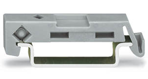
Figura:
End clip for DIN 35 fixed across the DIN rail
Installation in a cabinet
All RP-IO module models are recommended to be installed in a cabinet, unless local regulations allow an exception.
Aviso
The device should be installed within an enclosure such as a control cabinet for isolation to exposed live parts.
action_zoom_plus_stroke
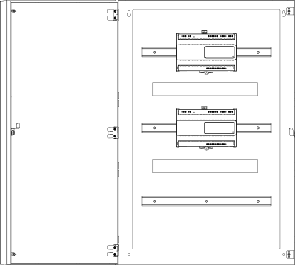
Figura:
RP-IO modules installed on horizontal DIN rails in a cabinet
When installing RP-IO modules in a cabinet, it is recommended to provide ample space between the DIN rails and modules for sufficient ventilation.
Screw terminals
The RP-IO modules have fixed screw terminals.
Para obtener más información, consulte RP-IO Screw Terminals
.
Anchor points for cable ties
The RP-IO modules have four anchor points that can be used to fasten cable ties or other accessories for bundling wires.
action_zoom_plus_stroke
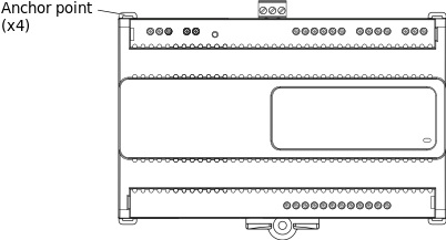
Figura:
Anchor points for cable ties
Optional covers
The RP-IO modules can be equipped with optional covers to reduce access to the screw terminals and wires if desired.
action_zoom_plus_stroke
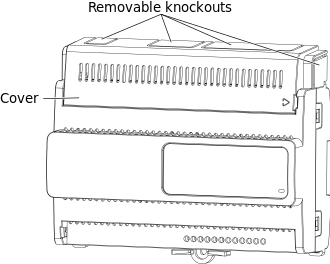
Figura:
Optional covers

 RP-IO Module Device Installation
 RP-IO Screw Terminals
 RP-IO-12A-M-24V Screw Terminals
 RP-IO-16E-M-24V Screw Terminals
 Wiring
 Powering Up an RP-IO Module


