Specifications
CRS-HH-REL-10

Introduction
SpaceLogic* CRS-HH-REL-10 relay module connects to the SpaceLogic RP room controllers and enables the control of lights and blinds.
It supports high-voltage (120/240 VAC) blind motors. Other types of blind motors are supported by means of external relays. For more information, see the SpaceLogic Hardware Reference Guide.
It is part of the EcoStruxure™ Connected Room Solutions for Hotels and can be combined with other modules from this product range.
It is designed for hotel guest room applications.
* Formerly known as SmartX.
Features
The relay module offers the following features:
Power and communications through the room bus
10 relay outputs for the control of lights and blinds in the hotel guest room
12 digital inputs offer more flexibility for different applications with in-wall switches or sensors. The digital inputs are SELV (Safety Extra-Low Voltage).
High-performance relays, with high inrush current capability, well suited for LED lighting applications
Status LED for the device
Rotary switch for address configuration
This solution easily transforms hotels. Its extensive architecture is designed for a wide range of modular components including temperature, light and blind control interfaces, as well as bedside panels, sensors, thermostats, plus a wide range of HMIs (such as mechanical switches and Modbus glass touch panels). Get the latest wireless capabilities with the eCommission SmartX Controllers mobile application for commissioning and the open protocols to interface with industry-standard IoT devices.
The RP-C room bus supports up to six connected RP controller expansion modules with the restrictions that are specified for the Connected Room Solutions for Hotels in the Architecture Guidelines - Hotel Application. This is a supplementary document to the Architectural Guidelines - EcoStruxure Building Management.
Maximum total length of the room bus is 72 m (236 ft).
|
Product |
Part number |
|
CRS-HH-REL-10 Includes pluggable screw terminal blocks (10 x 2-pole, 2 x 9-pole connectors) for the I/O, delivered in a plastic bag with the device. |
SXWHHREL10001
|
|
DIN-RAIL-CLIP, DIN-rail end clip
package of 25 pieces
|
SXWDINEND10001
|
Specifications
| Electrical | |
DC input supply voltage
|
24 VDC
|
Powered by the RP-C through the room bus (RJ45)
|
|
Maximum power consumption
|
0.3 W
|
| Environment | |
Ambient temperature, operating
|
0 to 50 °C (32 to 122 °F)
|
Ambient temperature, storage
|
-20 to +70 °C (-4 to +158 °F)
|
Humidity
|
20 to 90 % RH non-condensing
|
Pollution degree
|
2
|
| Material | |
Plastic flame rating
|
UL94 V-0
|
Ingress protection rating
|
IP 20
|
| Mechanical | |
Dimensions
|
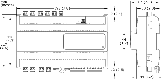
198 W x 110 H x 64 D mm (7.8 W x 4.3 H x 2.5 D in.)
|

|
|
Weight
|
0.476 kg (1.050 lb)
|
Installation
|
DIN rail or flat surface
|
Terminal blocks
|
Relay outputs: 10 x 2-pin screw terminal block
|
Digital inputs: 2 x 9-pin screw terminal block
|
|
| Software compatibility | |
EcoStruxure Building Operation software
|
version 3.3 and later
|
| Agency compliances | |
Emission
|
RCM; BS/EN 61000-6-3; BS/EN 50491-5-2; FCC Part 15, Sub-part B, Class B
|
Immunity
|
BS/EN 61000-6-2; BS/EN 50491-5-3
|
Safety standards
|
BS/EN 60730-1; BS/EN 60730-2-11; BS/EN 50491-3; UL 916 C-UL US Listed
|
Fire performance in air-handling spaces
a
|
UL 2043
|
| a) The CRS-HH-REL-10 relay module is approved for plenum applications. | |
| Communication ports | |
Room bus
|
RS-485
|
Dual RJ45 ports for daisy-chain configurations
|
|
Use a Cat 5 (or higher) cable
|
|
Maximum total length of the room bus: 72 m (236 ft)
|
|
Room bus protection
|
Transient voltage suppressors on communication and power signals
|
| Hardware | |
CPU type
|
ARM Cortex-M4 single-core
|
Frequency
|
80 MHz
|
SRAM (embedded)
|
320 KB
|
Flash memory (embedded)
|
512 KB
|
NOR flash memory
|
16 MB
|
Status indicator
|
LED (green and red) that shows the status of the device
|
Address switch
|
Rotary switch 0 to 9
|
Set button
|
Push-button switch
|
| Relay outputs | |
Outputs
|
10, DO1 to DO10
|
Relay output rating
|
24 to 277 VAC, 50/60 Hz, 30 VDC:
|
Resistive and incandescent: 10 A
|
|
Standard magnetic ballast: 5 A
|
|
LED driver: 5 A
|
|
1/2 HP, 240 VAC, 50/60 Hz
|
|
1/4 HP, 120 VAC, 50/60 Hz
|
|
Maximum load current
|
Maximum 50 A total load for the 10 outputs
|
Maximum inrush current
|
Maximum 165 A inrush current (<20 ms) per output
|
Maximum 800 A inrush current (<200 µs) per output
|
|
| Digital inputs | |
Inputs
|
12, DI1 to DI12
|
Range
|
Dry contact, 0 to 5.0 VDC, 2.2 mA, SELV (Safety Extra-Low Voltage)
|
Connections
Follow proper installation wiring diagrams and instructions. For more information on wiring, see the installation instructions in the SpaceLogic CRS-HH-REL-10 Expansion Module Installation Sheet, the SpaceLogic Hardware Reference Guide, and the RP-C room bus restrictions specified for the Connected Room Solutions for Hotels in the Architecture Guidelines - Hotel Application, which is a supplementary document to the Architectural Guidelines - EcoStruxure Building Management.

 RP-C
RP-C
 Commission