
Spezifikationen
SpaceLogic IP-IO

Einleitung
Das SpaceLogic™ IP-IO Modul bietet eine E/A-Erweiterung für Ihre HLK-Anwendung über BACnet/IP. Das Modul kann seine E/A-Ressourcen über Anwendungen teilen, die in Automation Servern, BACnet/IP-Controllern oder Systemen von Drittanbietern laufen. Mit der Unterstützung von lokalen Alarmen und Trendlogs vermeidet das IP-IO-Modul unnötigen Datenverkehr über das Netzwerk, während es wichtige Daten lokal speichern kann. Das IP-IO-Modul kann in der Nähe von Anlagen im Feld installiert werden, die weit entfernt vom Automation Server oder dem BACnet/IP-Controller sind. Alle IP-IO-Modelle unterstützen ein optionales Display, das Einblick und Steuerung der Ein- und Ausgänge ermöglicht.
Das IP-IO-Modul weist folgende Funktionen auf:
IP-fähig mit Dual-Port-Ethernet-Switch
BACnet/SC-Knoten
Vielseitiger E/A-Punktmix
Erweiterte Überwachung
Commission App für die Inbetriebnahme des Controllers bevor der BMS platziert wird
Umfassende Unterstützung der EcoStruxure Building Operation Software mit effizienten Engineering-Tools
Aktualisierung mit signierter Firmware
Informationen über die maximale Anzahl von IP-IO-Modulen, die mit einem Automation Server oder BACnet/IP-Controller verwendet werden können, finden Sie in den Architekturrichtlinien.
IP-Konnektivität, flexible Netzwerktopologien und Unterstützung für BACnet/SC-Anwendungen
The IP-IO module is based on open protocols that simplify interoperability, IP configuration, and device management, and can be enabled as BACnet/SC nodes for increased cybersecurity:
IP addressing
BACnet/IP or BACnet/SC communications
DHCP for easy network configuration
The IP-IO module has a dual-port Ethernet switch, which enables flexible network topologies:
Star
Daisy chain
Rapid Spanning Tree Protocol (RSTP) ring
In a star topology, the IP-IO module and the parent EcoStruxure BMS server are individually connected to an Ethernet switch. Daisy-chain multiple IP-IO modules together to reduce the installation time and cost. Use an RSTP ring topology when you want a non-operational IP-IO module to be detected and recovered quickly and efficiently.
BACnet/SC (Secure Connect-)Unterstützung
The IP-IO module supports BACnet/SC applications as a BACnet/SC node. This allows the IP-IO module to be used in a BACnet/SC network, which allows secure transport of BACnet traffic and information between BACnet/SC devices over private and public networks without the need for BBMDs, VLANs, and VPNs, because the BACnet/SC protocol uses WebSocket technology and TLS 1.3 encryption. In addition, BACnet/SC uses certificate management to help ensure only those devices authorized to be on a BACnet/SC network can operate on that network.
Modelle mit einem vielseitigen E/A-Punktemix
Das IP-IO-Modul wird in drei Versionen mit unterschiedlicher I/O-Anzahl und vielseitigen Datenpunkttypen angeboten, die zu einer breiten Palette von Anwendungen passen. Die universellen Eingänge/Ausgänge sind sehr flexibel und können als Ein- oder Ausgang konfiguriert werden.
|
I/O Point Types |
IP-IO-DI10 |
IP-IO-UIO10 |
IP-IO-UIO5DOFA4 |
|
Digital inputs |
10 |
- |
- |
|
Universal I/O Type Ub |
- |
10 |
5 |
|
Relay outputs Form A |
- |
- |
3 |
|
High power relay outputs Form A |
- |
- |
1 |
|
Configurations |
Digital Inputs |
Universal I/O Type Ub |
Relay Outputs Form A |
High Power Relay Outputs Form A |
|
Digital inputs |
yes |
yes |
- |
- |
|
Counter inputs |
yes |
yes |
- |
- |
|
Supervised inputs |
- |
yes |
- |
- |
|
Voltage inputs (0 to 10 VDC) |
- |
yes |
- |
- |
|
Current inputs (0 to 20 mA) |
- |
yes |
- |
- |
|
Temperature inputs |
- |
yes |
- |
- |
|
Resistive inputs |
- |
yes |
- |
- |
|
2-wire RTD temperature inputs |
- |
yes |
- |
- |
|
Voltage outputs (0 to 10 VDC) |
- |
yes |
- |
- |
|
Digital outputs |
- |
- |
yes |
yes |
|
Digital pulsed outputs |
- |
- |
yes |
yes |
|
PWM outputs |
- |
- |
yes |
yes |
|
Tristate outputs |
- |
- |
yes |
- |
|
Tristate pulsed outputs |
- |
- |
yes |
- |
The digital inputs can be used for cost effective sensing of multiple dry contact digital inputs in applications, such as equipment status monitoring or alarm point monitoring. As counter inputs, digital inputs are commonly used in energy metering applications.
The universal inputs/outputs are ideal for any mix of temperature, pressure, flow, status points, and similar point types in a building control system.
As counter inputs, the universal inputs/outputs are commonly used in energy metering applications. As RTD inputs, they are ideal for temperature points in a building control system. As supervised inputs, they are used for security applications where it is critical to know whether or not a wire has been cut or shorted. These events provide a separate indication of alarms and events in the system.
For all analog inputs, maximum and minimum levels can be defined to automatically detect over-range and under-range values.
Die Unversal-Ein- und Ausgänge können auch als Spannungsausgänge verwendet werden, ohne externe Bias-Widerstände zu erfordern. Daher unterstützen Universal-Ein-/Ausgänge eine Vielzahl von Geräten, wie zum Beispiel Aktoren.
The relay outputs support digital Form A point types. The Form A relays are designed for direct load applications.
The high power relay output is ideal for switching loads of up to 12 A, such as electrical heating elements.
Erweiterte Überwachung
The I/O module supports local trends and alarms, enabling local operation when the I/O module is offline.
With user-defined fallback values, the I/O module outputs will be in a predictable state in cases of network disruption.
The battery-free power backup of the memory and real-time clock helps prevent data loss and allows seamless and quick recovery after a power disruption.
Alle IP-IO-Modelle können mit einem optionalen Displaymodul geliefert werden (das gleiche Modul, das für den MP-C verwendet wird), das eine LCD-Anzeige und fünf Tasten umfasst. Mit diesem Modul können Sie Analog- und Digitalausgänge manuell übersteuern zum Testen, zur Inbetriebnahme und zur Wartung von Geräten, die an die Ausgänge angeschlossen sind. Die dedizierte Verarbeitungsleistung des Display-Moduls sichert zuverlässige Handschaltung für Wartungsanwendungen. Der Handschaltungsstatus kann von den Benutzerschnittstellen, wie der EcoStruxure Building Operation WorkStation und WebStation, angezeigt werden, was eine genauere Überwachung und Steuerung ermöglicht.

In WorkStation, you update the firmware of multiple I/O modules at the same time and with minimum down time. The EcoStruxure BMS server keeps track of the installed firmware to support backup, restore, and replacement of the I/O modules. The server can host I/O modules of different firmware versions.
Commission App
Die mobile Commission-App ist für die lokale Konfiguration, die Feldanwendung und die Inbetriebnahme von IP-IO-Modulen vorgesehen. Die App reduziert die Inbetriebnahmezeit, erlaubt Flexibilität bei der Durchführung des Projekts und minimiert Abhängigkeiten von der Netzwerk-Infrastruktur.
The mobile application is designed for use with Android, Apple (iOS), and Microsoft Windows 10 and Windows 11 devices. For more information, see the EcoStruxure Building Commission Specification Sheet.

Using the Commission mobile application, you can connect to IP-IO modules and BACnet/IP controllers over the network. Using a wireless access point or a network switch, you can connect to a network of IP-IO modules and BACnet/IP controllers on the local IP network.
With the Commission mobile application, you can easily discover IP-IO modules and BACnet/IP controllers on the IP network. You can change the configuration of each module and controller, including the BACnet and IP network settings, location, and parent server. To save engineering time, you can save common device settings and then reuse them for devices of the same type and model.
The Commission mobile application does not require an EcoStruxure BMS server or a network infrastructure to be in place. You can use the mobile application to load the IP-IO application directly into the local IP-IO module and deploy the IP-IO module. The IP-IO application can be created offline using Project Configuration Tool or WorkStation while preserving all external bindings to server and controller applications using the IP-IO module's I/O points. You can also perform an I/O checkout to ensure that the IP-IO module's I/O points are configured, wired, and operating correctly.
Kompletter EcoStruxure Building Operation-Software-Support
The power of the I/O module is fully realized when it is part of an EcoStruxure BMS, which provides the following benefits:
WorkStation/WebStation interface
Device discovery
Engineering efficiency
WorkStation and WebStation provide a consistent user experience regardless of which EcoStruxure BMS server the user is logged on to. The user can log on to the parent EcoStruxure BMS server to engineer, commission, supervise, and monitor the I/O modules and RP and MP controllers. For more information, see the WorkStation and WebStation specification sheets.
The enhanced Device Discovery in WorkStation enables you to easily identify the I/O modules on a BACnet network and to associate the I/O modules with their parent server.
The engineering and maintenance of the I/O modules can be done very efficiently using the EcoStruxure Building Operation reusability features. With these features, you can create library items (Custom Types) for a complete I/O module application that contains I/O point configurations and all necessary objects such as trends and alarms. The I/O module application in the Custom Types library is reusable across all I/O modules of the same model. You can use the I/O module application as a base for creating new I/O modules intended for similar applications. You can then edit the I/O module application, and the changes are automatically replicated to all I/O modules, while each I/O module keeps its local values.
WorkStation supports both online and offline engineering of the I/O modules. You can make the configuration changes online or use database mode to make the changes offline. In database mode, the changes are saved to the EcoStruxure Building Operation database so that you can apply the changes to the I/O modules later.
Project Configuration Tool enables you to perform all the engineering off site, without the need for physical hardware, which minimizes the time you need to spend on site. You can run the EcoStruxure BMS servers virtually and engineer the RP and MP controllers and the I/O modules before you deploy your server, controller, and I/O module applications to the servers, controllers, and I/O modules on site. For more information, see the Project Configuration Tool specification sheet.
Aktualisierung mit signierter Firmware
Using digitally signed firmware provides more secure upgrading of the device. During an upgrade, the device verifies that the firmware is authentic and uncompromised Schneider Electric firmware. If the device detects discrepancies in the authenticity or integrity of the firmware, it will reject the upgrade. Once the device is upgraded with signed firmware, all upgrades thereafter must be with a signed firmware version.
|
Produkt |
Artikelnummer |
|
IP-IO-DI10
|
SXWIPIOAA10001
|
|
IP-IO-UIO10
|
SXWIPIOBA10001
|
|
IP-IO-UIO5DOFA4
|
SXWIPIOCA10001
|
|
IP-IO-DI10-BAA a |
SXWIPIOAA10A01
|
|
IP-IO-UIO10-BAA a |
SXWIPIOBA10A01
|
|
IP-IO-UIO5DOFA4-BAA a |
SXWIPIOCA10A01
|
|
IP-IO-DI10-SMK b |
SXWIPIOAA1S001
|
|
IP-IO-UIO10-SMK b |
SXWIPIOBA1S001
|
|
IP-IO-UIO5DOFA4-SMK b |
SXWIPIOCA1S001
|
- Entspricht dem Buy American Act (BAA).
- Zugelassen für die Verwendung in UL 864 Rauchkontrollsystemen. Die Modelle mit Rauchkontrolle (SMK) werden mit einer validierten UL 864 Softwareversion ausgeliefert, die sich von der zuletzt veröffentlichten Software unterscheiden kann. Weitere Informationen über die zugelassenen Softwareversionen für das Gerät, wenn dieses in UL 864 Rauchkontrollsystemen verwendet wird, finden Sie im Dokument 01-16001-XX-en für die Softwareversionen des Rauchkontrollsystems – EcoStruxure Building Management.
|
Produkt |
Artikelnummer |
|
MP-CßDISPLAY a (MP-C Handschaltungs-Displaymodul) |
SXWMPCDSP10001
|
|
MP-C-BAA-DISPLAY b (MP-C-Handschaltungs-Displaymodul) |
SXWMPCDSP10A01
|
|
DIN-RAIL-CLIP, DIN-rail end clip
package of 25 pieces
|
SXWDINEND10001
|
- Zugelassen für die Verwendung in UL 864 Rauchkontrollsystemen.
- MP-C-BAA-DISPLAY ist ein Teil von Buy American Act (BAA) entsprechenden Bundles zusammen mit entweder dem MP-C-15A-BAA- oder dem MP-C-36A-BAA-Controller. MP-C-BAA-DISPLAY kann nur über die Artikelnummer des MP-C-15A-BAA-Bundles (SXWMPC15AB10A01) oder des MP-C-36A-BAA-Bundles (SXWMPC36AB10A01) bestellt werden. Das MP-C-BAA-DISPLAY unterscheidet sich in Hinsicht auf Hardware und Funktionalität nicht vom MP-C DISPLAY.
For more information on part numbers for Network Connectivity Accessories, see the Für weitere Informationen siehe Product Selection Guide - EcoStruxure Building ..
Spezifikationen
| AC input | |||||||||||||
Nominal voltage
|
24 VAC
|
||||||||||||
Operating voltage range
|
+/- 20 %
|
||||||||||||
Frequency
|
50/60 Hz
|
||||||||||||
Maximum power consumption
|
17 VA
|
||||||||||||
Power input protection
|
MOV suppression and internal fuse
|
||||||||||||
| DC input | |||||||||||||
Nominal voltage
|
24 to 30 VDC
|
||||||||||||
Operating voltage range
|
21 to 33 VDC
|
||||||||||||
Maximum power consumption
|
9 W
|
||||||||||||
Power input protection
|
MOV suppression and internal fuse
|
||||||||||||
| Environment | |||||||||||||
Ambient temperature, operating
|
0 to 50 °C (32 to 122 °F) at normal operation
a
|
||||||||||||
-40 to +60 °C (-40 to +140 °F) for rooftop applications, horizontal installation only
a
|
|||||||||||||
| a) MP-C Display has an operating temperature range of -30 to +60 °C (-22 to +140 °F). | |||||||||||||
Ambient temperature, storage
|
-40 to +70 °C (-40 to +158 °F)
|
||||||||||||
Maximum humidity
|
95 % RH non-condensing
|
||||||||||||
| Material | |||||||||||||
Plastic flame rating
|
UL94-5V
|
||||||||||||
Ingress protection rating
|
IP 20
|
||||||||||||
| Mechanical | |||||||||||||
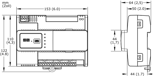
Dimensions
|
153 W x 110 H x 64 D mm (6.0 W x 4.3 H x 2.5 D in.)
|
||||||||||||
|
|||||||||||||
Weight, IP-IO-DI10
|
|||||||||||||
Including terminal blocks
|
0.337 kg (0.742 lb)
|
||||||||||||
Weight, IP-IO-UIO10
|
|||||||||||||
Including terminal blocks
|
0.336 kg (0.740 lb)
|
||||||||||||
Weight, IP-IO-UIO5DOFA4
|
|||||||||||||
Including terminal blocks
|
0.357 kg (0.787 lb)
|
||||||||||||
Recommended installation
|
DIN rail or flat surface in a cabinet
a
|
||||||||||||
| a) It is recommended to install the device in an enclosure (cabinet), unless local regulations allow an exception. | |||||||||||||
Terminal blocks
|
Removable
|
||||||||||||
| Compatibility | |||||||||||||
EcoStruxure BMS server communication
|
|||||||||||||
EcoStruxure Building Operation
|
version 2.0.4 and later
|
||||||||||||
BACnet/SC network support
|
|||||||||||||
EcoStruxure Building Operation
|
version 6.0.1 and later
|
||||||||||||
EcoStruxure Building Management Smoke Control System
a
|
|||||||||||||
EcoStruxure Building Operation
|
For information, see the Smoke Control System Approved Software Revisions - EcoStruxure Building Management document, 01-16001-XX-en.
|
||||||||||||
| a) Applies to the Smoke Control (SMK) models. | |||||||||||||
| Agency compliances | |||||||||||||
Emission
|
RCM; BS/EN 61000-6-3; BS/EN IEC 63044-5-2; FCC Part 15, Sub-part B, Class B
|
||||||||||||
Immunity
|
BS/EN 61000-6-2; BS/EN IEC 63044-5-3
|
||||||||||||
Safety standards
|
BS/EN 60730-1; BS/EN 60730-2-11; BS/EN IEC 63044-3; UL 916 C-UL US Listed
|
||||||||||||
Smoke control product safety
a
|
UL 864
|
||||||||||||
| a) Applies to the Smoke Control (SMK) models and MP-C DISPLAY module. For specifications and information on the restrictions that apply to the SMK models and display module when used in UL 864 smoke control systems, see the EcoStruxure Building Management - Smoke Control System Design Guide, 04-16014-XX-en. | |||||||||||||
| Real-time clock | |||||||||||||
Accuracy, at 25 °C (77 °F)
|
+/-1 minute per month
|
||||||||||||
Backup time, at 25 °C (77 °F)
|
7 days minimum
|
||||||||||||
| Communication ports | |||||||||||||
Ethernet
|
Dual 10/100BASE-TX (RJ45), IEEE 802.3 compliant
|
||||||||||||
USB
|
1 USB 2.0 device port (mini-B)
|
||||||||||||
1 USB 2.0 host port (type-A), 5 VDC, 2.5 W
|
|||||||||||||
| Communications | |||||||||||||
BACnet
|
BACnet/IP, port configurable, default 47808
|
||||||||||||
BACnet/SC, port configurable, no default port
|
|||||||||||||
BTL B-ASC (BACnet Application Specific Controller)
a
|
|||||||||||||
| a) See the BTL Product Catalog for up-to-date details on BTL listed firmware revisions on BACnet International's home page. | |||||||||||||
| CPU | |||||||||||||
Frequency
|
500 MHz
|
||||||||||||
Type
|
ARM Cortex-A7 dual-core
|
||||||||||||
DDR3 SDRAM
|
128 MB
|
||||||||||||
NOR flash memory
|
32 MB
|
||||||||||||
Memory backup
|
128 kB, FRAM, non-volatile
|
||||||||||||
| MP-C Display (Optional) | |||||||||||||
Removable
|
No
|
||||||||||||
Display size
|
36 W x 17 H mm (1.4 W x 0.7 H in.)
|
||||||||||||
Display resolution
|
128 x 64 pixels
|
||||||||||||
Display type
|
FSTN monochrome LCD, white color transflective backlight
|
||||||||||||
Power consumption
|
max. 0.15 W (45 mA at 3.3 V)
|
||||||||||||
Ambient temperature, operating
|
-30 to +60 °C (-22 to +140 °F)
|
||||||||||||
Ambient temperature, storage
|
-40 to +70 °C (-40 to +158 °F)
|
||||||||||||
Maximum humidity
|
95 % RH non-condensing
|
||||||||||||
Weight
|
0.035 kg (0.077 lb)
|
||||||||||||
Compliance mit Normen
|
EN ISO 16484-2
|
||||||||||||
| Digital inputs, DI | |||||||||||||
Channels, IP-IO-DI10
|
10, DI1 to DI10
|
||||||||||||
Channels, IP-IO-UIO10
|
0
|
||||||||||||
Channels, IP-IO-UIO5DOFA4
|
0
|
||||||||||||
Absolute maximum ratings
|
-0.5 to +24 VDC
|
||||||||||||
Digital input protection
|
Transient voltage suppressor on each digital input
|
||||||||||||
| Digital inputs | |||||||||||||
Range
|
Dry contact switch closure or open collector/open drain, 24 VDC, typical wetting current 2.4 mA
|
||||||||||||
Minimum pulse width
|
150 ms
|
||||||||||||
| Counter inputs | |||||||||||||
Range
|
Dry contact switch closure or open collector/open drain, 24 VDC, typical wetting current 2.4 mA
|
||||||||||||
Minimum pulse width
|
20 ms
|
||||||||||||
Maximum frequency
|
25 Hz
|
||||||||||||
| Universal inputs/outputs, Ub | |||||||||||||
Channels, IP-IO-DI10
|
0
|
||||||||||||
Channels, IP-IO-UIO10
|
10 Ub, Ub1 to Ub10
|
||||||||||||
Channels, IP-IO-UIO5DOFA4
|
5 Ub, Ub1 to Ub5
|
||||||||||||
Absolute maximum ratings
|
-0.5 to +24 VDC
|
||||||||||||
A/D converter resolution
|
16 bits
|
||||||||||||
Universal input/output protection
|
Transient voltage suppressor on each universal input/output
|
||||||||||||
| Digital inputs | |||||||||||||
Range
|
Dry contact switch closure or open collector/open drain, 24 VDC, typical wetting current 2.4 mA
|
||||||||||||
Minimum pulse width
|
150 ms
|
||||||||||||
| Counter inputs | |||||||||||||
Range
|
Dry contact switch closure or open collector/open drain, 24 VDC, typical wetting current 2.4 mA
|
||||||||||||
Minimum pulse width
|
20 ms
|
||||||||||||
Maximum frequency
|
25 Hz
|
||||||||||||
| Supervised inputs | |||||||||||||
5 V circuit, 1 or 2 resistors
|
|||||||||||||
Monitored switch combinations
|
Series only, parallel only, and series and parallel
|
||||||||||||
Resistor range
|
1 to 10 kohm
|
||||||||||||
| For a 2-resistor configuration, each resistor must have the same value +/- 5 % | |||||||||||||
| Voltage inputs | |||||||||||||
Range
|
0 to 10 VDC
|
||||||||||||
Accuracy
|
+/-(7 mV + 0.2 % of reading)
|
||||||||||||
Resolution
|
1.0 mV
|
||||||||||||
Impedance
|
100 kohm
|
||||||||||||
| Current inputs | |||||||||||||
Range
|
0 to 20 mA
|
||||||||||||
Accuracy
|
+/-(0.01 mA + 0.4 % of reading)
|
||||||||||||
Resolution
|
1 μA
|
||||||||||||
Impedance
|
47 ohm
|
||||||||||||
| Resistive inputs | |||||||||||||
10 ohm to 10 kohm accuracy
|
+/-(7 + 4 x 10
-3
x R) ohm
|
||||||||||||
| R = Resistance in ohm | |||||||||||||
10 kohm to 60 kohm accuracy
|
+/-(4 x 10
-3
x R + 7 x 10
-8
x R
2
) ohm
|
||||||||||||
| R = Resistance in ohm | |||||||||||||
| Temperature inputs (thermistors) | |||||||||||||
Range
|
-50 to +150 °C (-58 to +302 °F)
|
||||||||||||
| Supported thermistors | |||||||||||||
Honeywell
|
20 kohm
|
||||||||||||
Type I (Continuum)
|
10 kohm
|
||||||||||||
Type II (I/NET)
|
10 kohm
|
||||||||||||
Type III (Satchwell)
|
10 kohm
|
||||||||||||
Type IV (FD)
|
10 kohm
|
||||||||||||
Type V (FD w/ 11k shunt)
|
Linearized 10 kohm
|
||||||||||||
Satchwell D?T
|
Linearized 10 kohm
|
||||||||||||
Johnson Controls
|
2.2 kohm
|
||||||||||||
Xenta
|
1.8 kohm
|
||||||||||||
Balco
|
1 kohm
|
||||||||||||
| Measurement accuracy | |||||||||||||
20 kohm
|
-50 to -30 °C: +/-1.5 °C (-58 to -22 °F: +/-2.7 °F)
|
||||||||||||
-30 to 0 °C: +/-0.5 °C (-22 to +32 °F: +/-0.9 °F)
|
|||||||||||||
0 to 100 °C: +/-0.2 °C (32 to 212 °F: +/-0.4 °F)
|
|||||||||||||
100 to 150 °C: +/-0.5 °C (212 to 302 °F: +/-0.9 °F)
|
|||||||||||||
10 kohm, 2.2 kohm, and 1.8 kohm
|
-50 to -30 °C: +/-0.75 °C (-58 to -22 °F: +/-1.35 °F)
|
||||||||||||
-30 to +100 °C: +/-0.2 °C (-22 to +212 °F: +/-0.4 °F)
|
|||||||||||||
100 to 150 °C: +/-0.5 °C (212 to 302 °F: +/-0.9 °F)
|
|||||||||||||
Linearized 10 kohm
|
-50 to -30 °C: +/-2.0 °C (-58 to -22 °F: +/-3.6 °F)
|
||||||||||||
-30 to 0 °C: +/-0.75 °C (-22 to +32 °F: +/-1.35 °F)
|
|||||||||||||
0 to 100 °C: +/-0.2 °C (32 to 212 °F: +/-0.4 °F)
|
|||||||||||||
100 to 150 °C: +/-0.5 °C (212 to 302 °F: +/-0.9 °F)
|
|||||||||||||
1 kohm
|
-50 to +150 °C: +/-1.0 °C (-58 to +302° F: +/-1.8 °F)
|
||||||||||||
| RTD temperature inputs | |||||||||||||
Supported RTDs
|
Pt1000, Ni1000, and LG-Ni1000
|
||||||||||||
| Pt1000 | |||||||||||||
Sensor range
|
-50 to +150 °C (-58 to +302 °F)
|
||||||||||||
|
|||||||||||||
| Ni1000 | |||||||||||||
Sensor range
|
-50 to +150 °C (-58 to +302 °F)
|
||||||||||||
|
|||||||||||||
| LG-Ni1000 | |||||||||||||
Sensor range
|
-50 to +150 °C (-58 to +302 °F)
|
||||||||||||
|
|||||||||||||
| RTD temperature wiring | |||||||||||||
Maximum wire resistance
|
20 ohm/wire (40 ohm total)
|
||||||||||||
Maximum wire capacitance
|
60 nF
|
||||||||||||
| The wire resistance and capacitance typically corresponds to a 200 m wire. | |||||||||||||
| Voltage outputs | |||||||||||||
Range
|
0 to 10 VDC
|
||||||||||||
Accuracy
|
+/-60 mV
|
||||||||||||
Resolution
|
10 mV
|
||||||||||||
Minimum load resistance
|
5 kohm
|
||||||||||||
Load range
|
-1 to +2 mA
|
||||||||||||
| Relay outputs, DO | |||||||||||||
Channels, IP-IO-DI10
|
0
|
||||||||||||
Channels, IP-IO-UIO10
|
0
|
||||||||||||
Channels, IP-IO-UIO5DOFA4
|
3, DO1 to DO3
|
||||||||||||
Contact rating
|
250 VAC/30 VDC, 2 A, Pilot Duty (C300)
|
||||||||||||
Switch type
|
Form A Relay
|
||||||||||||
Single Pole Single Throw
|
|||||||||||||
Normally Open
|
|||||||||||||
Isolation contact to system ground
|
3000 VAC
|
||||||||||||
Cycle life (Resistive load)
|
At least 100,000 cycles
|
||||||||||||
Minimum pulse width
|
100 ms
|
||||||||||||
| High power relay outputs, DO | |||||||||||||
Channels, IP-IO-DI10
|
0
|
||||||||||||
Channels, IP-IO-UIO10
|
0
|
||||||||||||
Channels, IP-IO-UIO5DOFA4
|
1, DO4
|
||||||||||||
Contact rating
|
250 VAC/24 VDC, 12 A, Pilot Duty (B300)
|
||||||||||||
Switch type
|
Form A Relay
|
||||||||||||
Single Pole Single Throw
|
|||||||||||||
Normally Open
|
|||||||||||||
Isolation contact to system ground
|
5000 VAC
|
||||||||||||
Cycle life (Resistive load)
|
At least 100,000 cycles
|
||||||||||||
Minimum pulse width
|
100 ms
|
||||||||||||
Anschlüsse
Follow proper installation wiring diagrams and instructions, including these instructions:
All IP-IO models have several RET terminals for connection of I/O returns, so a common chassis/signal ground rail is optional and may not be needed.
Individual 24 V power sources to the field must be current limited to maximum 4 A for UL compliant installations, and maximum 6 A in other areas.
For more information on wiring, see Hardware Reference Guide.


 Enterprise Server
SpaceLogic AS-P
SpaceLogic AS-B
WorkStation
WebStation
SpaceLogic MP-C Pro
SpaceLogic MP-V
Commission
Project Configuration Tool – Version 2
Automated Engineering Tool
Enterprise Server
SpaceLogic AS-P
SpaceLogic AS-B
WorkStation
WebStation
SpaceLogic MP-C Pro
SpaceLogic MP-V
Commission
Project Configuration Tool – Version 2
Automated Engineering Tool
 Architectural Guidelines 7.0.1