earth_america
user_standard Connexion
action_search_stroke
earth_america
Log on to rate and give feedback 1 2 3 4 5 Log on to rate
0
Comment faire pour

Comment faire pour


Produits : RP-C
Fonctionnalités : Matériel
Version produit : 2022, 2023, 2024, 7.0
11/03/2022

Wiring a Screw Terminal on an RP Controller Expansion Zigbee Module

You wire the screw terminals on an RP controller expansion Zigbee module to connect lights and LEDs as well as power (220–240 VAC) to the electrical ballasts and drivers for the lights and LEDs. Always use the recommended wires (or wires with larger cross-sectional area).

Afficher plus
action_close

The RP controller expansion Zigbee modules are designed to be installed on a flat surface on a ceiling.

The Zigbee modules must be professionally installed to comply with the following rules and regulations:

  • 2014/53/EU Radio Equipment Directive (RED) of the European Union (EU)

  • UK Statutory Instruments 2017 No. 1206 – The Radio Equipment Regulations 2017

Pour plus d'informations, voir Zigbee Modules Regulatory Compliance and Approvals .

The Zigbee module and its integrated antenna must be installed to provide a separation distance of at least 20 cm (8 in.) from all persons and must not be co-located or operating in conjunction with any other antenna or transmitter. Information on recommended RF exposure limits can be obtained from Health Canada's website, www.canada.ca/en/health-canada .

Précaution Précaution

RADIO FREQUENCY (RF) EXPOSURE

  • Install the Zigbee module and its antenna at least 20 cm (8 in.) from all persons.

  • Do not install the Zigbee module with its integrated antenna near any other antenna or radio transmitter.

Failure to follow these instructions can result in minor or moderate injury.

Déclaration

REDUCED RADIO COVERAGE RANGE

Do not route power or high-voltage cables close to the Zigbee module's integrated antenna, which is in the lower right area of the device.

Failure to follow these instructions can result in reduced device performance.

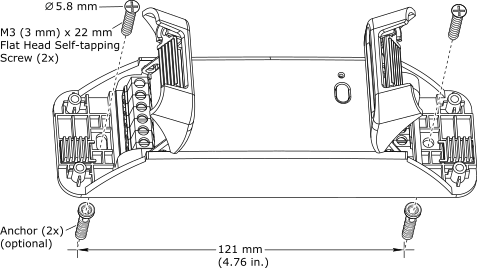
To install a Zigbee module on a ceiling, you drill two holes in the ceiling with a distance of 121 mm (4.7 inches) between the holes, and fasten the device using two M3 (3 mm) x 22 mm Phillips flat head self-tapping screws with a 5.8 mm screw head diameter. The device has two holes in the back cover to facilitate installation. The two screws are delivered with the device. Pour plus d'informations, voir Installing an RP Controller Expansion Zigbee Module on a Ceiling .

 
action_zoom_plus_stroke Installing a Zigbee module on a ceiling
Figure : Installing a Zigbee module on a ceiling

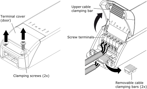
The screw terminals on the left and right side of the Zigbee module are covered by two terminal covers (doors), which are intended to reduce the access to the screw terminals and wires. To open or close a terminal cover, you need to unscrew or screw in the two clamping screws. These two screws are also used to fasten the cables to the device. The device is equipped with an upper cable clamping bar on the inside of the terminal covers, and four lower cable clamping bars are delivered with the device, to facilitate the fastening of the cables. The lower, removable cable clamping bars can be mounted or removed to fit cables of smaller or larger diameter. Pour plus d'informations, voir Wiring a Screw Terminal on an RP Controller Expansion Zigbee Module .

Danger Danger

HAZARD OF ELECTRIC SHOCK, EXPLOSION, OR ARC FLASH

Disconnect the power supply and other high voltage equipment before wiring.

Failure to follow these instructions will result in death or serious injury.

 
action_zoom_plus_stroke Wiring a screw terminal on a Zigbee module
Figure : Wiring a screw terminal on a Zigbee module

Afficher plus
action_close

The wiring recommendations provide guidance regarding wiring of the Central IO modules, automation servers, RP and MP controllers, IP-IO and RP-IO modules, RP controller expansion modules, and Operator Display.

I/O Wiring

The I/O wiring recommendations provide guidance on what type of wires should be used for the different Central IO modules, AS-B server onboard I/O, RP and MP controller onboard I/O, and IP-IO and RP-IO I/O modules, how to perform grounding, and how to connect different external devices to the inputs and outputs. This section also provides information on the external connectors required for the RP controller expansion modules and the RP-C-16C-F-230V model. Always use the recommended cables and wires.

Pour plus d'informations, voir I/O Wiring .

Communication Port Wiring

The wiring recommendations for the communication ports on the automation servers, RP and MP controllers, IP-IO and RP-IO modules, RP controller expansion modules, and Operator Display devices apply to wires and cables used for RS-485 communications, LonWorks communications, USB connections, Ethernet connections, sensor bus connections, room bus connections, and RP and MP controller Modbus network connections. Always use the recommended cables and wires.

Pour plus d'informations, voir Communication Port Wiring .

Danger Danger

HAZARD OF ELECTRIC SHOCK, EXPLOSION, OR ARC FLASH

Disconnect the power supply and other high voltage equipment before wiring.

Failure to follow these instructions will result in death or serious injury.

To wire a screw terminal on an RP controller expansion Zigbee module
  1. Disconnect the power supply and other high voltage equipment connected to the Zigbee module.

  2. Loosen the two screws that hold the green terminal cover in place and then open the cover.

     
    action_zoom_plus_stroke
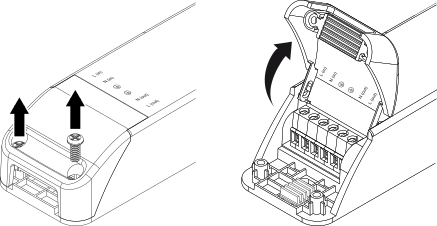
  3. Loosen the screw of the terminal.

  4. Strip approximately 8 to 9 mm (0.31 to 0.35 inch) of the insulation from the end of each wire.

  5. Insert the end of the wire fully into its intended terminal. Ensure that no bare wire strands extend from the terminal.

  6. Tighten the screw using a small flat-blade screwdriver. Ensure that the screw is fully tightened. Use the following recommended screw tightening torque: 0.50 Nm (4.4 lbf.in).

     
    action_zoom_plus_stroke
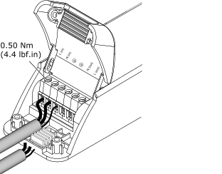
  7. Ensure that the cable outer sheath (insulation) is aligned with the upper and lower cable clamping bars.

  8. Remove the lower cable clamping bars to accommodate larger diameter cables.

     
    action_zoom_plus_stroke
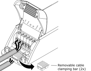
  9. Close the cover and then tighten the two screws. Ensure that the screws are fully tightened. Use the following recommended screw tightening torque: 0.59 Nm (5.2 lbf.in).

     
    action_zoom_plus_stroke
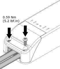
  10. Use appropriate cable strain relief methods, especially for wires that carry 30 VAC or 42.4 VDC or above, to help prevent any load applied to the cable from being transferred to conductor terminations.

  • Zigbee Modules Device Installation
  • Wiring